DEMO9S08JM16 Freescale Semiconductor, DEMO9S08JM16 Datasheet - Page 301
DEMO9S08JM16
Manufacturer Part Number
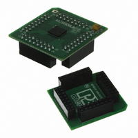
DEMO9S08JM16
Description
BOARD DEMO FOR JM16 FAMI
Manufacturer
Freescale Semiconductor
Type
MCUr
Datasheets
1.DEMO9S08JM16.pdf
(47 pages)
2.DEMO9S08JM16.pdf
(5 pages)
3.DEMO9S08JM16.pdf
(4 pages)
4.DEMO9S08JM16.pdf
(386 pages)
Specifications of DEMO9S08JM16
Contents
Board with Daughter card, Cable, Documentation, Mini-AB USB Kit
Processor To Be Evaluated
MC9S08JM16
Data Bus Width
8 bit
Interface Type
USB
Silicon Manufacturer
Freescale
Core Architecture
HCS08
Core Sub-architecture
HCS08
Silicon Core Number
MC9S08
Silicon Family Name
Flexis - S08JM
Rohs Compliant
Yes
For Use With/related Products
MC9S08JM16
Lead Free Status / RoHS Status
Lead free / RoHS Compliant


17.3.1
USBRESMEN
17.3.2
The PERID reads back the value of 0x04. This value is defined for the USB module peripheral.
Freescale Semiconductor
USBPHYEN
USBRESET
USBVREN
LPRESF
USBPU
Reset
Field
7
6
5
4
2
0
W USBRESET
R
USB Control Register 0 (USBCTL0)
Peripheral ID Register (PERID)
0
0
7
USB Reset — This bit generates a hard reset of the USB module, USBPHYEN and USBVREGEN bits will also
be cleared. (need remember to restart USB Transceiver and USB voltage regulator).
When set to 1, this bit automatically clears when the reset occurs.
0 USB module normal operation
1 Returns the USB module to its reset state
Pull Up Source — This bit determines the source of the pullup resistor on the USBDP line.
0 Internal USBDP pullup resistor is disabled; The application can use an external pullup resistor
1 Internal USBDP pullup resistor is enabled
USB Low-Power Resume Event Enable — This bit, when set, enables the USB module to send an
asynchronous wakeup interrupt to the MCU upon detection that the LPRESF bit has been set, indicating
a K-state on the USB bus. This bit must be set before entering low-power stop3 mode only after SLEEPF=1 (USB
is entering suspend mode). It must be cleared immediately after stop3 recovery in order to clear the Low-Power
Resume Flag.
0 USB asynchronous wakeup from suspend mode disabled
1 USB asynchronous wakeup from suspend mode enabled
Low-Power Resume Flag — This bit becomes set in USB suspend mode if USBRESMEN=1 and a K-state is
detected on the USB bus, indicating resume signaling while the device is in a low-power stop3 mode. This flag
bit will trigger an asynchronous interrupt, which will wake the device from stop3. Firmware must then clear the
USBRESMEN bit in order to clear the LPRESF bit.
0 No K-state detected on the USB bus while the device is in stop3 and the USB is suspended.
1 K-state detected on the USB bus when USBRESMEN=1, the device is in stop3, and the USB is suspended.
USB Voltage Regulator Enable — This bit enables the on-chip 3.3 V USB voltage regulator.
0 On-chip USB voltage regulator is disabled (OFF MODE)
1 On-chip USB voltage regulator is enabled for active or standby mode
USB Transceiver Enable — When the USB Transceiver (XCVR) is disabled, USBDP and USBDN are hi-Z. It is
recommended that the XCVR be enabled before setting the USBEN bit in the CTL register. The firmware must
ensure that the XCVR remains enabled when entering USB SUSPEND mode.
0 On-chip XCVR is disabled
1 On-chip XCVR is enabled
Figure 17-3. USB Transceiver and Regulator Control Register 0 (USBCTL0)
= Unimplemented or Reserved
USBPU
0
6
Table 17-4. USBCTL0 Field Descriptions
USBRESMEN
MC9S08JM16 Series Data Sheet, Rev. 2
0
5
LPRESF
0
4
Description
3
0
0
Universal Serial Bus Device Controller (S08USBV1)
USBVREN
0
2
0
0
1
USBPHYEN
0
0
301
Related parts for DEMO9S08JM16
Image
Part Number
Description
Manufacturer
Datasheet
Request
R

Part Number:
Description:
Manufacturer:
Freescale Semiconductor, Inc
Datasheet:
Part Number:
Description:
Manufacturer:
Freescale Semiconductor, Inc
Datasheet:
Part Number:
Description:
Manufacturer:
Freescale Semiconductor, Inc
Datasheet:
Part Number:
Description:
Manufacturer:
Freescale Semiconductor, Inc
Datasheet:
Part Number:
Description:
Manufacturer:
Freescale Semiconductor, Inc
Datasheet:
Part Number:
Description:
Manufacturer:
Freescale Semiconductor, Inc
Datasheet:
Part Number:
Description:
Manufacturer:
Freescale Semiconductor, Inc
Datasheet:
Part Number:
Description:
Manufacturer:
Freescale Semiconductor, Inc
Datasheet:
Part Number:
Description:
Manufacturer:
Freescale Semiconductor, Inc
Datasheet:
Part Number:
Description:
Manufacturer:
Freescale Semiconductor, Inc
Datasheet:
Part Number:
Description:
Manufacturer:
Freescale Semiconductor, Inc
Datasheet:
Part Number:
Description:
Manufacturer:
Freescale Semiconductor, Inc
Datasheet:
Part Number:
Description:
Manufacturer:
Freescale Semiconductor, Inc
Datasheet:
Part Number:
Description:
Manufacturer:
Freescale Semiconductor, Inc
Datasheet:
Part Number:
Description:
Manufacturer:
Freescale Semiconductor, Inc
Datasheet: