DEMO9S08JM16 Freescale Semiconductor, DEMO9S08JM16 Datasheet - Page 295
DEMO9S08JM16
Manufacturer Part Number
DEMO9S08JM16
Description
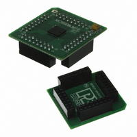
BOARD DEMO FOR JM16 FAMI
Manufacturer
Freescale Semiconductor
Type
MCUr
Datasheets
1.DEMO9S08JM16.pdf
(47 pages)
2.DEMO9S08JM16.pdf
(5 pages)
3.DEMO9S08JM16.pdf
(4 pages)
4.DEMO9S08JM16.pdf
(386 pages)
Specifications of DEMO9S08JM16
Contents
Board with Daughter card, Cable, Documentation, Mini-AB USB Kit
Processor To Be Evaluated
MC9S08JM16
Data Bus Width
8 bit
Interface Type
USB
Silicon Manufacturer
Freescale
Core Architecture
HCS08
Core Sub-architecture
HCS08
Silicon Core Number
MC9S08
Silicon Family Name
Flexis - S08JM
Rohs Compliant
Yes
For Use With/related Products
MC9S08JM16
Lead Free Status / RoHS Status
Lead free / RoHS Compliant


Chapter 17
Universal Serial Bus Device Controller (S08USBV1)
17.1
This chapter describes an universal serial bus device controller (S08USBV1) module that is based on the
Universal Serial Bus Specification Rev 2.0. The USB bus is designed to replace existing bus interfaces
such as RS-232, PS/2, and IEEE 1284 for PC peripherals.
The S08USBV1 module provides a single-chip solution for full-speed (12 Mbps) USB device applica-
tions, and integrates the required transceiver with Serial Interface Engine (SIE), 3.3 V regulator, Endpoint
RAM and other control logics.
17.1.1
The S08USBV1 requires two clock sources, the 24 MHz bus clock and a 48 MHz reference clock. The
48 MHz clock is sourced directly from MCGOUT. To achieve the 48 MHz clock rate, the MCG must be
configured properly for PLL engaged external (PEE) mode with an external crystal.
For USB operation, examples of MCG configuration using PEE mode include:
17.1.2
In USB suspend mode, the S08USBV1 current consumption is limited to 500 μA. When the USB device
goes into suspend mode, the firmware typically enters stop3 to meet the USB suspend requirements on
current consumption.
17.1.3
If using an external 3.3 V regulator as an input to V
V
(USBVREN = 1), do not connect an external supply to the V
3.9 V and 5.5 V for the internal 3.3 V regulator to operate correctly.
Freescale Semiconductor
DD
•
•
, must not fall below the input voltage at the V
2 MHz crystal – RDIV = 000 and VDIV = 0110
4 MHz crystal – RDIV = 001 and VDIV = 0110
Introduction
Clocking Requirements
Current Consumption in USB Suspend
3.3 V Regulator
Enabling LVD increases current consumption in stop3. Consequently, when
trying to satisfy USB suspend requirements, disabling LVD before entering
stop3.
MC9S08JM16 Series Data Sheet, Rev. 2
NOTE
USB33
USB33
(only when USBVREN = 0), the supply voltage,
pin. If using the internal 3.3 V regulator
USB33
pin. In this case, V
DD
must fall between
295
Related parts for DEMO9S08JM16
Image
Part Number
Description
Manufacturer
Datasheet
Request
R

Part Number:
Description:
Manufacturer:
Freescale Semiconductor, Inc
Datasheet:
Part Number:
Description:
Manufacturer:
Freescale Semiconductor, Inc
Datasheet:
Part Number:
Description:
Manufacturer:
Freescale Semiconductor, Inc
Datasheet:
Part Number:
Description:
Manufacturer:
Freescale Semiconductor, Inc
Datasheet:
Part Number:
Description:
Manufacturer:
Freescale Semiconductor, Inc
Datasheet:
Part Number:
Description:
Manufacturer:
Freescale Semiconductor, Inc
Datasheet:
Part Number:
Description:
Manufacturer:
Freescale Semiconductor, Inc
Datasheet:
Part Number:
Description:
Manufacturer:
Freescale Semiconductor, Inc
Datasheet:
Part Number:
Description:
Manufacturer:
Freescale Semiconductor, Inc
Datasheet:
Part Number:
Description:
Manufacturer:
Freescale Semiconductor, Inc
Datasheet:
Part Number:
Description:
Manufacturer:
Freescale Semiconductor, Inc
Datasheet:
Part Number:
Description:
Manufacturer:
Freescale Semiconductor, Inc
Datasheet:
Part Number:
Description:
Manufacturer:
Freescale Semiconductor, Inc
Datasheet:
Part Number:
Description:
Manufacturer:
Freescale Semiconductor, Inc
Datasheet:
Part Number:
Description:
Manufacturer:
Freescale Semiconductor, Inc
Datasheet: