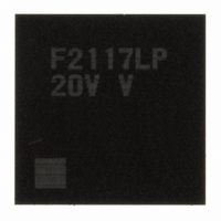
DF2117VLP20V Renesas Electronics America, DF2117VLP20V Datasheet - Page 41

DF2117VLP20V
Manufacturer Part Number
DF2117VLP20V
Description
IC H8S/2117 MCU FLASH 145TFLGA
Manufacturer
Renesas Electronics America
Series
H8® H8S/2100r
Datasheet
1.DF2117VBG20V.pdf
(960 pages)
Specifications of DF2117VLP20V
Core Processor
H8S/2600
Core Size
16-Bit
Speed
20MHz
Connectivity
FIFO, I²C, LPC, SCI, SmartCard
Peripherals
POR, PWM, WDT
Number Of I /o
112
Program Memory Size
160KB (160K x 8)
Program Memory Type
FLASH
Ram Size
8K x 8
Voltage - Supply (vcc/vdd)
3 V ~ 3.6 V
Data Converters
A/D 16x10b
Oscillator Type
External
Operating Temperature
-20°C ~ 75°C
Package / Case
145-TFLGA
For Use With
HS0005KCU11H - EMULATOR E10A-USB H8S(X),SH2(A)3DK2166 - DEV EVAL KIT H8S/2166
Lead Free Status / RoHS Status
Lead free / RoHS Compliant
Eeprom Size
-
Available stocks
Company
Part Number
Manufacturer
Quantity
Price
Company:
Part Number:
DF2117VLP20V
Manufacturer:
Renesas
Quantity:
100
Part Number:
DF2117VLP20V
Manufacturer:
RENESAS/瑞萨
Quantity:
20 000
- Current page: 41 of 960
- Download datasheet (6Mb)
Section 16 Serial Communication Interface with FIFO (SCIF) ........................467
16.1 Features.............................................................................................................................. 467
16.2 Input/Output Pins ............................................................................................................... 469
16.3 Register Descriptions ......................................................................................................... 470
16.4 Operation ........................................................................................................................... 488
16.5 Interrupt Sources................................................................................................................ 502
16.6 Usage Note......................................................................................................................... 502
Section 17 I
17.1 Features.............................................................................................................................. 503
17.2 Input/Output Pins ............................................................................................................... 507
17.3 Register Descriptions ......................................................................................................... 508
15.9.8 Note on Writing to Registers in Transmission, Reception, and
16.3.1 Receive Shift Register (FRSR) ............................................................................. 471
16.3.2 Receive Buffer Register (FRBR) .......................................................................... 471
16.3.3 Transmitter Shift Register (FTSR)........................................................................ 472
16.3.4 Transmitter Holding Register (FTHR).................................................................. 472
16.3.5 Divisor Latch H, L (FDLH, FDLL) ...................................................................... 472
16.3.6 Interrupt Enable Register (FIER) .......................................................................... 473
16.3.7 Interrupt Identification Register (FIIR)................................................................. 474
16.3.8 FIFO Control Register (FFCR) ............................................................................. 476
16.3.9 Line Control Register (FLCR) .............................................................................. 477
16.3.10 Modem Control Register (FMCR) ........................................................................ 478
16.3.11 Line Status Register (FLSR) ................................................................................. 480
16.3.12 Modem Status Register (FMSR)........................................................................... 484
16.3.13 Scratch Pad Register (FSCR)................................................................................ 485
16.3.14 SCIF Control Register (SCIFCR) ......................................................................... 486
16.4.1 Baud Rate.............................................................................................................. 488
16.4.2 Operation in Asynchronous Communication........................................................ 489
16.4.3 Initialization of the SCIF ...................................................................................... 490
16.4.4 Data Transmission/Reception with Flow Control................................................. 493
16.4.5 Data Transmission/Reception Through the LPC Interface ................................... 499
16.6.1 Power-Down Mode When LCLK Is Selected for SCLK ...................................... 502
16.6.2 FLCR Access During Serial Transmission and Reception ................................... 502
17.3.1 I
17.3.2 Slave Address Register (SAR) .............................................................................. 510
17.3.3 Second Slave Address Register (SARX) .............................................................. 511
17.3.4 I
Simultaneous Transmission and Reception .......................................................... 466
2
2
2
C Bus Data Register (ICDR) .............................................................................. 509
C Bus Mode Register (ICMR)............................................................................ 513
C Bus Interface (IIC) .....................................................................503
Rev. 3.00 Sep. 28, 2009 Page xxxix of xliv
REJ09B0350-0300
Related parts for DF2117VLP20V
Image
Part Number
Description
Manufacturer
Datasheet
Request
R

Part Number:
Description:
KIT STARTER FOR M16C/29
Manufacturer:
Renesas Electronics America
Datasheet:

Part Number:
Description:
KIT STARTER FOR R8C/2D
Manufacturer:
Renesas Electronics America
Datasheet:

Part Number:
Description:
R0K33062P STARTER KIT
Manufacturer:
Renesas Electronics America
Datasheet:

Part Number:
Description:
KIT STARTER FOR R8C/23 E8A
Manufacturer:
Renesas Electronics America
Datasheet:

Part Number:
Description:
KIT STARTER FOR R8C/25
Manufacturer:
Renesas Electronics America
Datasheet:

Part Number:
Description:
KIT STARTER H8S2456 SHARPE DSPLY
Manufacturer:
Renesas Electronics America
Datasheet:

Part Number:
Description:
KIT STARTER FOR R8C38C
Manufacturer:
Renesas Electronics America
Datasheet:

Part Number:
Description:
KIT STARTER FOR R8C35C
Manufacturer:
Renesas Electronics America
Datasheet:

Part Number:
Description:
KIT STARTER FOR R8CL3AC+LCD APPS
Manufacturer:
Renesas Electronics America
Datasheet:

Part Number:
Description:
KIT STARTER FOR RX610
Manufacturer:
Renesas Electronics America
Datasheet:

Part Number:
Description:
KIT STARTER FOR R32C/118
Manufacturer:
Renesas Electronics America
Datasheet:

Part Number:
Description:
KIT DEV RSK-R8C/26-29
Manufacturer:
Renesas Electronics America
Datasheet:

Part Number:
Description:
KIT STARTER FOR SH7124
Manufacturer:
Renesas Electronics America
Datasheet:

Part Number:
Description:
KIT STARTER FOR H8SX/1622
Manufacturer:
Renesas Electronics America
Datasheet:

Part Number:
Description:
KIT DEV FOR SH7203
Manufacturer:
Renesas Electronics America
Datasheet:


