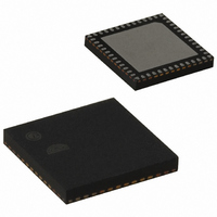
EM357-RTR Ember, EM357-RTR Datasheet - Page 193

EM357-RTR
Manufacturer Part Number
EM357-RTR
Description
IC RF TXRX ZIGBEE 192KB 48QFN
Manufacturer
Ember
Specifications of EM357-RTR
Frequency
2.4GHz
Data Rate - Maximum
250kbps
Modulation Or Protocol
802.15.4 Zigbee
Applications
General Purpose
Power - Output
5dBm
Sensitivity
-100dBm
Voltage - Supply
2.1 V ~ 3.6 V
Current - Receiving
26mA
Current - Transmitting
31mA
Data Interface
PCB, Surface Mount
Memory Size
192kB Flash, 12kB RAM
Antenna Connector
PCB, Surface Mount
Operating Temperature
-40°C ~ 85°C
Package / Case
48-QFN
Lead Free Status / RoHS Status
Lead free / RoHS Compliant
Other names
636-1011-2
Available stocks
Company
Part Number
Manufacturer
Quantity
Price
Company:
Part Number:
EM357-RTR
Manufacturer:
SILICON
Quantity:
3 000
Part Number:
EM357-RTR
Manufacturer:
SILICON
Quantity:
20 000
- Current page: 193 of 245
- Download datasheet (12Mb)
ADC_CFG
ADC Configuration Register
Bitname
ADC_PERIOD
ADC_CFGRSVD2
ADC_MUXP
ADC_MUXN
ADC_1MHZCLK
ADC_CFGRSVD
ADC_ENABLE
ADC_MUXP
31
23
15
0
0
7
ADC_PERIOD
30
22
14
6
0
0
Bitfield
[15:13]
[12:11]
[10:7]
[6:3]
[2]
[1]
[0]
29
21
13
5
0
0
Access
RW
RW
RW
RW
RW
RW
RW
ADC_MUXN
ADC sample time in clocks and the equivalent significant bits in the conversion.
Select ADC clock: 0 = 6 MHz, 1 = 1 MHz.
Reserved: this bit must always be set to 0.
Description
0: 32 clocks (7 bits).
1: 64 clocks (8 bits).
2: 128 clocks (9 bits).
3: 256 clocks (10 bits).
4: 512 clocks (11 bits).
5: 1024 clocks (12 bits).
6: 2048 clocks (13 bits).
7: 4096 clocks (14 bits).
Reserved: these bits must be set to 0.
Input selection for the P channel.
0x0: PB5 pin.
0x1: PB6 pin.
0x2: PB7 pin.
0x3: PC1 pin.
0x4: PA4 pin.
0x5: PA5 pin.
0x8: GND (0V) (not for high voltage range).
0x9: VREF/2 (0.6V).
0xA: VREF (1.2V).
0xB: VDD_PADSA/2 (0.9V) (not for high voltage range).
0x6, 0x7, 0xC-0xF: reserved.
Input selection for the N channel.
Refer to ADC_MUXP above for choices.
Enable the ADC: write 1 to enable continuous conversions, write 0 to stop.
When the ADC is started the first conversion takes twice the usual number of clocks plus
21 microseconds. If anything in this register is modified while the ADC is running, the next
conversion takes twice the usual number of clocks.
28
20
12
4
0
0
ADC_CFGRSVD2
10-14
Final
27
19
11
3
0
0
Address: 0x4000D004 Reset: 0x00001800
ADC_1MHZCLK
26
18
10
0
0
2
EM351 / EM357
ADC_CFGRSVD
ADC_MUXP
25
17
0
0
9
1
120-035X-000G
ADC_ENABLE
24
16
0
0
8
0
Related parts for EM357-RTR
Image
Part Number
Description
Manufacturer
Datasheet
Request
R

Part Number:
Description:
MODULE EM357 PA/LNA W/ANT TG
Manufacturer:
Ember
Datasheet:

Part Number:
Description:
MODULE EM357 NO PA/LNA W/ANT TG
Manufacturer:
Ember
Datasheet:

Part Number:
Description:
MODULE EM357 NO PA/LNA W/RF CONN
Manufacturer:
Ember
Datasheet:

Part Number:
Description:
MODULE EM357 PA/LNA W/RF CONN
Manufacturer:
Ember
Datasheet:

Part Number:
Description:
IC RF TXRX ZIGBEE 192KB 48QFN
Manufacturer:
Ember
Datasheet:

Part Number:
Description:
KIT DEV EMBER ZIGBEE W/PCWH
Manufacturer:
Custom Computer Services Inc (CCS)

Part Number:
Description:
PROGRAMMER USB FLASH EM250/260
Manufacturer:
Ember
Datasheet:

Part Number:
Description:
IC ZIGBEE SYSTEM-ON-CHIP 40-QFN
Manufacturer:
Ember
Datasheet:

Part Number:
Description:
IC ZIGBEE SYSTEM-ON-CHIP 48-QFN
Manufacturer:
Ember
Datasheet:

Part Number:
Description:
IC RF TXRX ZIGBEE 128KB 48QFN
Manufacturer:
Ember
Datasheet:

Part Number:
Description:
INSIGHT ADAPTER FOR EM2XX
Manufacturer:
Ember
Datasheet:

Part Number:
Description:
PROGRAMMER USB FLASH EM250/260
Manufacturer:
Ember
Datasheet:

Part Number:
Description:
IC ZIGBEE SYSTEM-ON-CHIP 40-QFN
Manufacturer:
Ember
Datasheet:

Part Number:
Description:
IC ZIGBEE SYSTEM-ON-CHIP 48-QFN
Manufacturer:
Ember
Datasheet:

Part Number:
Description:
IC RF TXRX ZIGBEE 128KB 48QFN
Manufacturer:
Ember
Datasheet:


