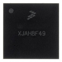
MC13224V Freescale Semiconductor, MC13224V Datasheet - Page 14

MC13224V
Manufacturer Part Number
MC13224V
Description
ZIGBEE PLATFORM 802.15.4 145-LGA
Manufacturer
Freescale Semiconductor
Datasheet
1.1322XUSB.pdf
(54 pages)
Specifications of MC13224V
Frequency
2.4GHz
Data Rate - Maximum
250kbps
Modulation Or Protocol
802.15.4 Zigbee
Applications
General Purpose
Power - Output
4dBm
Sensitivity
-100dBm
Voltage - Supply
2 V ~ 3.6 V
Current - Receiving
24mA
Current - Transmitting
29mA
Data Interface
PCB, Surface Mount
Memory Size
128kB Flash, 96kB RAM
Antenna Connector
PCB, Surface Mount
Operating Temperature
-40°C ~ 105°C
Package / Case
145-LGA
Number Of Receivers
1
Number Of Transmitters
1
Wireless Frequency
2.4 GHz
Interface Type
4-Wire SPI, I2C
Output Power
1.5 dBm
Operating Supply Voltage
2 V to 3.6 V
Maximum Operating Temperature
+ 105 C
Mounting Style
SMD/SMT
Maximum Supply Current
31 mA
Minimum Operating Temperature
- 40 C
Modulation
OQPSK
Protocol Supported
802.15.4
No. Of Pins
99
Supply Voltage Range
2V To 3.6V
Operating Temperature Range
-40°C To +125°C
Msl
MSL 3 - 168 Hours
A/d Converter
12 Bits
No. Of Timers 8/12/16/32 Bits
0 / 0 / 4 / 0
Rohs Compliant
Yes
Lead Free Status / RoHS Status
Lead free / RoHS Compliant
Available stocks
Company
Part Number
Manufacturer
Quantity
Price
Company:
Part Number:
MC13224V
Manufacturer:
Freescale Semiconductor
Quantity:
1 849
Company:
Part Number:
MC13224VR2
Manufacturer:
EPCOS
Quantity:
34 000
3.3.2.2
The CRM has primary control of the entire system:
3.3.3
For battery based applications, an optional buck regulator is provided to maximize battery life.
shows the configuration of the buck regulator versus the normal connection. An onboard MOSFET is used
as a switch with an external 100μH inductor and 10μF capacitor when the buck regulator is enabled.
The buck regulator drops the higher battery voltage to 1.8 - 2.0 Vdc that is applied to the onboard linear
regulators. This allows lower net current from the battery to maximize the life of the battery.
14
•
•
•
•
•
Reset and power up — After release of the hardware RESETB signal, the CRM will perform a
power up sequence of the MCU. The linear regulators and clock sources are managed for a graceful
start-up of the MCU and its resources. The radio is not powered until needed
Normal operation of MCU — The clock management of the MCU and its resources are controlled
by the CRM. The processor clock is programmable from low frequencies up to the maximum
reference frequency (13-26 MHz optional w/24 MHz standard) to allow the application to trade-off
processing speed versus power savings
Sleep modes and recovery — There are two sleep modes of Hibernate and Doze. The primary
difference is that Doze mode keeps the reference oscillator running. Both modes can retain critical
programmed parameters and have selectable sizes of RAM retention. Hibernate has lowest power,
but Doze allows high accuracy sleep timing. The CRM manages the recovery from low power,
similar to power-up from reset, providing regulator and clock management.
— Wake-up can be based on external interrupts through 4 KBI inputs
— Wake-up can be from internal interrupts
— Wake-up can be based on an RTI (wake-up) timer.
The RTI timer has two possible frequency sources that provide a very low power wake-up option
from sleep
— One option is an onboard, low accuracy 2 kHz oscillator
— A second option is to add an external 32.768 kHz crystal for the RTI clock source
— A 32-bit timer allows greater than a 36.4 hour wake-up delay with the 32.768 crystal oscillator
Other features of the CRM:
— An optional COP watchdog timer to monitor CPU program activity
— A programmable software reset
Optional Buck Regulator
CRM Operation
MC1322x Technical Data, Rev. 1.3
Freescale Semiconductor
Figure 4


