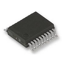
UPD78F9222MC(T)-5A4-A NEC, UPD78F9222MC(T)-5A4-A Datasheet - Page 102

UPD78F9222MC(T)-5A4-A
Manufacturer Part Number
UPD78F9222MC(T)-5A4-A
Description
8BIT MCU, 4K FLASH, 256B RAM, 78F9222
Manufacturer
NEC
Datasheet
1.UPD78F9222MCT-5A4-A.pdf
(414 pages)
Specifications of UPD78F9222MC(T)-5A4-A
Controller Family/series
UPD78
No. Of I/o's
17
Ram Memory Size
256Byte
Cpu Speed
10MHz
No. Of Timers
4
No. Of
RoHS Compliant
Core Size
8bit
Program Memory Size
4KB
Oscillator Type
External, Internal
Available stocks
Company
Part Number
Manufacturer
Quantity
Price
Company:
Part Number:
UPD78F9222MC(T)-5A4-A
Manufacturer:
NEC
Quantity:
1 000
Company:
Part Number:
UPD78F9222MC(T)-5A4-A
Manufacturer:
NEC/PBF
Quantity:
6 640
Part Number:
UPD78F9222MC(T)-5A4-A
Manufacturer:
RENESAS/瑞萨
Quantity:
20 000
- Current page: 102 of 414
- Download datasheet (4Mb)
102
CR010 capture value
Note The carry flag is set to 1. Ignore this setting.
(2) Measurement of two pulse widths with free-running counter
TM00 count value
TI000 pin input
When 16-bit timer counter 00 (TM00) is operated in free-running mode, it is possible to simultaneously
measure the pulse widths of the two signals input to the TI000 pin and the TI010 pin.
Specify both the rising and falling edges as the valid edges of the TI000 and TI010 pins, by using bits 4 and 5
(ES000 and ES010) and bits 6 and 7 (ES100 and ES110) of PRM00.
When the valid edge specified by bits 4 and 5 (ES000 and ES010) of PRM00 is input to the TI000 pin, the
value of TM00 is taken into 16-bit timer capture/compare register 000 (CR010) and an interrupt request signal
(INTTM010) is set.
Also, when the valid edge specified by bits 6 and 7 (ES100 and ES110) of PRM00 is input to the TI010 pin, the
value of TM00 is taken into 16-bit timer capture/compare register 000 (CR000) and an interrupt request signal
(INTTM000) is set.
Sampling is performed using the count clock cycle selected by prescaler mode register 00 (PRM00), and a
capture operation is only performed when a valid level of the TI000 or TI010 pin is detected twice, thus
eliminating noise with a short pulse width.
INTTM010
Count clock
Figure 6-19. Configuration Diagram for Pulse Width Measurement by Free-Running Counter
Figure 6-20. Timing of Pulse Width Measurement Operation by Free-Running Counter
TI000/INTP0/P30
0000H
t
and One Capture Register (with Both Edges Specified)
f
f
XP
XP
0001H
/2
/2
f
XP
2
6
CHAPTER 6 16-BIT TIMER/EVENT COUNTER 00
D0
(D1 − D0) × t
D0
User’s Manual U16898EJ5V0UD
D0 + 1
16-bit timer capture/compare
register 010 (CR010)
D1
16-bit timer/counter 00
D1
Internal bus
D1 + 1
(TM00)
(D2 − D1) × t
FFFFH
0000H
Note
INTTM010
D2
(D3 − D2) × t
D2
D3
D3
Related parts for UPD78F9222MC(T)-5A4-A
Image
Part Number
Description
Manufacturer
Datasheet
Request
R

Part Number:
Description:
16/8 bit single-chip microcomputer
Manufacturer:
NEC
Datasheet:

Part Number:
Description:
Dual audio power amp circuit
Manufacturer:
NEC
Datasheet:

Part Number:
Description:
Dual comparator
Manufacturer:
NEC
Datasheet:

Part Number:
Description:
MOS type composite field effect transistor
Manufacturer:
NEC
Datasheet:

Part Number:
Description:
50 V/100 mA FET array incorporating 2 N-ch MOSFETs
Manufacturer:
NEC
Datasheet:

Part Number:
Description:
6-pin small MM high-frequency double transistor
Manufacturer:
NEC
Datasheet:

Part Number:
Description:
6-pin small MM high-frequency double transistor
Manufacturer:
NEC
Datasheet:

Part Number:
Description:
6-pin small MM high-frequency double transistor
Manufacturer:
NEC
Datasheet:

Part Number:
Description:
6-pin small MM high-frequency double transistor
Manufacturer:
NEC
Datasheet:

Part Number:
Description:
Twin transistors equipped with different model chips(6P small MM)
Manufacturer:
NEC
Datasheet:

Part Number:
Description:
Bipolar analog integrated circuit
Manufacturer:
NEC
Datasheet:


