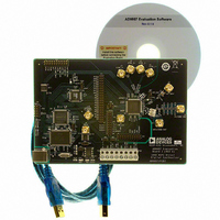
AD9957/PCBZ Analog Devices Inc, AD9957/PCBZ Datasheet - Page 24

AD9957/PCBZ
Manufacturer Part Number
AD9957/PCBZ
Description
D/A Converter Evaluation Board
Manufacturer
Analog Devices Inc
Series
AgileRF™r
Datasheet
1.AD9957BSVZ-REEL.pdf
(64 pages)
Specifications of AD9957/PCBZ
Silicon Manufacturer
Analog Devices
Application Sub Type
Direct Digital Synthesizer
Kit Application Type
Clock & Timing
Silicon Core Number
AD9957
Kit Contents
Board
Main Purpose
Timing: DDS Modulators
Embedded
No
Utilized Ic / Part
AD9957
Primary Attributes
14-Bit DAC, 32-Bit Tuning Word Width
Secondary Attributes
1GHz, Graphical User Interface
Lead Free Status / RoHS Status
Lead free / RoHS Compliant
Available stocks
Company
Part Number
Manufacturer
Quantity
Price
Company:
Part Number:
AD9957/PCBZ
Manufacturer:
LT
Quantity:
962
AD9957
Knowledge of the frequency response of the half-band filters is
essential to understanding their impact on the spectral properties
of the input signal. This is especially true when using the quad-
rature modulator to upconvert a baseband signal containing
complex data symbols that have been pulse shaped.
Consider that a complex symbol is represented by a real (I) and
an imaginary (Q) component, thus requiring two digital words
to represent a single complex sample of the form I + jQ. The
sample rate associated with a sequence of complex symbols is
referred to as f
the sample rate must be increased by some integer factor, M
(a consequence of the pulse shaping process). This new sample
rate (f
where f
to the input of the first half-band filter in both (I and Q) signal
paths. This rate should not be confused with the rate at which
data is supplied to the AD9957.
Typically, pulse shaping is applied to the baseband symbols via
a filter having a raised cosine response. In such cases, an excess
bandwidth factor (α, 0 ≤ α ≤ 1) is used to modify the bandwidth
of the data. For α = 0, the data bandwidth corresponds to f
for α = 1, the data bandwidth extends to f
the relationship between α, the bandwidth of the raised cosine
response, and the response of the first half-band filter.
The responses in Figure 36 reflect the specific case of M = 2 (the
interpolation factor for the pulse shaping operation). Increasing
Factor M shifts the location of the f
α = 1
NYQUIST
WIDTH
α = 0
BAND
HALF-BAND
RESPONSE
f
IQ
FILTER
IQ
½f
½f
IQ
) is related to the symbol rate by
= Mf
SYMBOL
SYMBOL
is the rate at which complex samples must be supplied
Figure 36. Effect of the Excess Bandwidth Factor (α)
SYMBOL
RAISED COSINE
SPECTRAL MASK
0.4
TYPICAL SPECTRUM OF A RANDOM SYMBOL SEQUENCE
SYMBOL
α = 0.5
f
IQ
f
f
SYMBOL
SYMBOL
½f
. If pulse shaping is applied to the symbols,
IQ
RATE OF FIRST
INPUT SAMPLE
HALF-BAND
FILTER
IQ
2
SAMPLE RATE FOR
2
2× OVERSAMPLED
f
f
PULSE SHAPING
SYMBOL
SYMBOL
point on the half-band
f
IQ
SYMBOL
INPUT SAMPLE
RATE OF FIRST
HALF-BAND
FILTER
. Figure 36 shows
3
4
f
f
SYMBOL
SYMBOL
SYMBOL
2
f
IQ
f
f
f
Rev. B | Page 24 of 64
/2;
response portion of the diagram to the right, as it must remain
aligned with the corresponding Mf
axis of the raised cosine spectral diagram. However, if f
to the right, so does the half-band response, proportionally.
The result is that the raised cosine spectral mask always lies
within the flat portion (dc to 0.4 f
of the first half-band filter, regardless of the choice of α so long
as M > 2. Therefore, for M > 2, the first half-band filter has
absolutely no negative impact on the spectrum of the baseband
signal when raised cosine pulse shaping is employed. For the
case of M = 2, a problem can arise. This is highlighted by the
shaded area in the tail of the α = 1 trace on the raised cosine
spectral mask diagram. Notice that this portion of the raised
cosine spectral mask extends beyond the flat portion of the
half-band response and causes unwanted amplitude and phase
distortion as the signal passes through the first half-band filter.
To avoid this, simply ensure that α ≤ 0.6 when M = 2.
PROGRAMMABLE INTERPOLATING FILTER
The programmable interpolator is implemented as a low-pass
CCI filter. It is programmable by a 6-bit control word, giving a
range of 2× to 63× interpolation.
The programmable interpolator is bypassed when programmed
for an interpolation factor of 1. When bypassed, power to the
stage is removed and the inverse CCI filter is also bypassed,
because its compensation is not needed.
The output of the programmable interpolator is the data from
the 4× interpolator further upsampled by the CCI filter, accord-
ing to the rate chosen by the user. This results in the upsampling of
the input data by a factor of 8× to 252× in steps of four.
The transfer function of the CCI interpolating filter is
where R is the programmed interpolation factor, and f is the
frequency normalized to f
Note that minimum R requirements exist depending on the
mode and frequency of f
defined under the follo wing conditions.
QDUC Mode
If f
If f
BFI Mode
If f
R is 3.
If f
R is 2.
If f
SYSCLK
SYSCLK
SYSCLK
SYSCLK
SYSCLK
H
( )
is between 500 MSPS to 1 GSPS, then the minimum R is 2.
is less than 500 MSPS, then the minimum R is 1.
is between 500 MSPS to 750 MSPS, then the minimum
is between 250 MSPS to 500 MSPS, then the minimum
is less than 250 MSPS, then the minimum R is 1.
f
=
R
k
∑
=
−
0
1
e
−
j
(
2
π
fk
)
SYSCLK
5
SYSCLK
. The minimum R setting is
.
IQ
SYMBOL
) of the pass band response
point on the frequency
IQ
shifts
(1)


