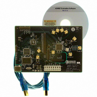
AD9957/PCBZ Analog Devices Inc, AD9957/PCBZ Datasheet - Page 27

AD9957/PCBZ
Manufacturer Part Number
AD9957/PCBZ
Description
D/A Converter Evaluation Board
Manufacturer
Analog Devices Inc
Series
AgileRF™r
Datasheet
1.AD9957BSVZ-REEL.pdf
(64 pages)
Specifications of AD9957/PCBZ
Silicon Manufacturer
Analog Devices
Application Sub Type
Direct Digital Synthesizer
Kit Application Type
Clock & Timing
Silicon Core Number
AD9957
Kit Contents
Board
Main Purpose
Timing: DDS Modulators
Embedded
No
Utilized Ic / Part
AD9957
Primary Attributes
14-Bit DAC, 32-Bit Tuning Word Width
Secondary Attributes
1GHz, Graphical User Interface
Lead Free Status / RoHS Status
Lead free / RoHS Compliant
Available stocks
Company
Part Number
Manufacturer
Quantity
Price
Company:
Part Number:
AD9957/PCBZ
Manufacturer:
LT
Quantity:
962
RAM CONTROL
RAM OVERVIEW
The AD9957 has an integrated 1024 × 32-bit RAM. This RAM
is only accessible when the AD9957 is operating in QDUC or
interpolating DAC mode. The RAM has two fundamental
modes of operation: data entry/retrieve mode and playback
mode. The mode is selected by programming the RAM Enable
bit in CFR1 via the serial I/O port.
Data entry/retrieve mode is used to load or read back the RAM
contents via the serial I/O port. Playback mode is used to deliver
RAM data to one of two internal destinations: the baseband
scaling multipliers (see Figure 25, the IS and QS labels) or the
baseband signal chain (see Figure 25, the I and Q labels). In
both cases, the RAM can be used to apply an arbitrary, time-
varying waveform to the selected destination. A block diagram
of the RAM and its control elements is shown in Figure 39.
The external parallel data port is disabled when the baseband
signal chain serves as the RAM playback destination.
In Figure 39, the serial I/O port is used to program the contents
of the two RAM segment registers as well as to load and retrieve
the RAM contents. The state machine takes care of incrementing
or decrementing the RAM address locations and controlling the
timing of the RAM address and data for proper operation. The
I-channel and Q-channel multiplexers route RAM data to base-
band scaling multipliers (IS/QS) or directly to the baseband
signal chain (I/Q) when the RAM is used in playback mode.
The state of the RAM playback destination bit determines the
destination of the RAM data during playback.
An I/O update (or a profile change) is necessary to enact a state
change of the RAM enable or RAM playback destination bits, or
any of the RAM segment register bits.
The 32-bit RAM data bus is partitioned so that the 16 MSBs are
designated as I-channel bits and the 16 LSBs are designated as
MACHINE
STATE
CLK
16
10
UP/DOWN COUNTER
10
3
RAM MODE
ADDRESS STEP RATE
START ADDRESS
END ADDRESS
U/D
Q CHANNEL
Q
I CHANNEL
10
Figure 39. RAM Block Diagram
DDS CLOCK
BASEBAND DATA CLOCK
RAM
QS
IS
Q
I
(MSBs)
(LSBs)
32
16
16
32
REGISTERS
SEGMENT
RAM
RT
SDIO
SDO
SCLK
I/O_RESET
CS
Rev. B | Page 27 of 64
Q-channel bits. In playback mode, when driving data directly
into the baseband signal chain, the 16-bit data-words are
considered to be signed (that is, twos complement) values. The
16-bit I-and Q-words are MSB aligned with the 18-bit I and Q
baseband data path. The two remaining LSBs of each 18-bit
baseband channel are driven by the MSB of the respective
channel. This ensures correct polarity coding when the 16-bit I
and Q data from the RAM translates into 18-bit words for the
baseband signal chain. Alternatively, when the RAM is driving
the baseband scaling multipliers in playback mode, the RAM
data is considered to represent unsigned, fractional values with a
range of 0 to 1 − 2
RAM SEGMENT REGISTERS
Two dedicated registers (RAM Segment Register 0 and RAM
Segment Register 1) control the operation of the RAM. Each
contains the following:
•
•
•
•
When programming these registers, the user must ensure that
the end address is greater than the start address.
With the RAM segment registers, the user can arbitrarily partition
the RAM into two independent memory segments. The segment
boundaries are specified with the start and end address words
in each RAM segment register. The playback rate is controlled
by the address step rate word (only meaningful when the base-
band scaling multipliers serve as the playback destination). If the
baseband signal chain serves as the RAM playback destination,
the 16-bit address step rate words must be set to 1. The playback
mode of the RAM is controlled via the RAM playback mode word.
RAM STATE MACHINE
The state machine acts as an address generator for the RAM. It
is clocked by either the serial I/O port (when the RAM is operating
in the load/retrieve mode) or the baseband data clock (when
the RAM is in playback mode). The state machine uses the
RAM mode bits of the active RAM segment register to establish
the proper sequence through the specified address range.
RAM TRIGGER (RT) PIN
The RAM state machine monitors the RT pin for logic state tran-
sitions. Any state transition triggers the state machine into action.
The direction of the logic state transition on the RT pin deter-
mines which RAM segment register the state machine uses for
playback instructions. RAM Segment Register 0 is used if the
state machine detects a 0-to-1 transition; RAM Segment Register 1
is used if a 1-to-0 transition is detected.
10-bit start address word
10-bit end address word
16-bit address step rate word
3-bit RAM playback mode word
−16
.
AD9957


