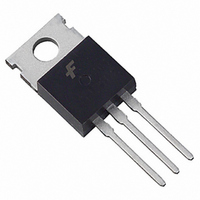
SGP5N60RUFDTU Fairchild Semiconductor, SGP5N60RUFDTU Datasheet - Page 5

SGP5N60RUFDTU
Manufacturer Part Number
SGP5N60RUFDTU
Description
IGBT W/DIODE 600V 5A
Manufacturer
Fairchild Semiconductor
Datasheet
1.SGP5N60RUFDTU.pdf
(8 pages)
Specifications of SGP5N60RUFDTU
Voltage - Collector Emitter Breakdown (max)
600V
Vce(on) (max) @ Vge, Ic
2.8V @ 15V, 5A
Current - Collector (ic) (max)
8A
Power - Max
60W
Input Type
Standard
Mounting Type
Through Hole
Package / Case
TO-220-3 (Straight Leads)
Channel Type
N
Configuration
Single
Collector-emitter Voltage
600V
Gate To Emitter Voltage (max)
±20V
Package Type
TO-220
Pin Count
3 +Tab
Mounting
Through Hole
Operating Temperature (min)
-55
Operating Temperature (max)
150C
Operating Temperature Classification
Military
Lead Free Status / RoHS Status
Lead free / RoHS Compliant
Igbt Type
-
Lead Free Status / Rohs Status
Compliant
©2002 Fairchild Semiconductor Corporation
1000
Fig 13. Switching Loss vs. Collector Current
Fig 15. SOA Characteristic
100
50
0.1
3
Common Emitter
V
T
T
Single Nonrepetitive
Pulse T
Curves must be derated
linearly with increase
in temperature
Ic MAX. (Pulsed)
Ic MAX. (Continuous)
C
C
GE
= 25℃ ━━
= 125℃ ------
= ± 15V, R
4
C
= 25℃
Collector-Emitter Voltage, V
Eoff
1
G
5
= 40
0.01
Collector Current, I
0.1
10
1
10
DC Operation
0.5
0.05
0.02
0.2
0.1
0.01
-5
6
10
single pulse
7
Fig 17. Transient Thermal Impedance of IGBT
10
C
[A]
-4
8
1㎳
CE
100
[V]
100us
9
Eon
50us
10
1000
Rectangular Pulse Duration [sec]
10
-3
10
-2
Fig 16. Turn-Off SOA Characteristics
Fig 14. Gate Charge Characteristics
40
15
12
9
6
3
0
0
1
Common Emitter
R
T
C
L
= 60
= 25℃
10
-1
3
Collector-Emitter Voltage, V
Pdm
V
Gate Charge, Q
10
Duty factor D = t1 / t2
Peak Tj = Pdm
CC
6
Safe Operating Area
V
GE
= 100V
= 20V, T
10
t1
0
t2
9
C
= 100℃
Zthjc + T
g
[nC]
100
12
C
10
CE
1
200V
300V
[V]
15
SGP5N60RUFD Rev. A1
1000
18


