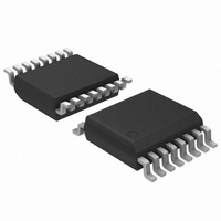
ADT7475ARQZ ON Semiconductor, ADT7475ARQZ Datasheet - Page 23

ADT7475ARQZ
Manufacturer Part Number
ADT7475ARQZ
Description
IC REMOTE THERMAL CTRLR 16-QSOP
Manufacturer
ON Semiconductor
Series
dBCool®r
Datasheet
1.ADT7475ARQZ.pdf
(58 pages)
Specifications of ADT7475ARQZ
Function
Fan Control, Temp Monitor
Topology
ADC, Comparator, Fan Speed Counter, Multiplexer, Register Bank
Sensor Type
External & Internal
Sensing Temperature
-40°C ~ 125°C, External Sensor
Output Type
SMBus™
Output Alarm
No
Output Fan
Yes
Voltage - Supply
3 V ~ 3.6 V
Operating Temperature
-40°C ~ 125°C
Mounting Type
Surface Mount
Package / Case
16-QSOP
Full Temp Accuracy
+/- 0.5 C
Digital Output - Bus Interface
Serial (3-Wire, 4-Wire)
Maximum Operating Temperature
+ 125 C
Minimum Operating Temperature
- 40 C
Lead Free Status / RoHS Status
Lead free / RoHS Compliant
Available stocks
Company
Part Number
Manufacturer
Quantity
Price
Part Number:
ADT7475ARQZ
Manufacturer:
ADI/亚德诺
Quantity:
20 000
Company:
Part Number:
ADT7475ARQZ-REEL7
Manufacturer:
SANYO
Quantity:
2 970
Part Number:
ADT7475ARQZ-REEL7
Manufacturer:
ADI/亚德诺
Quantity:
20 000
Part Number:
ADT7475ARQZ-RL7
Manufacturer:
ON/安森美
Quantity:
20 000
Driving up to Three Fans from PWM3
particular PWM channels; for example, TACH1 is
synchronized to PWM1. TACH3 and TACH4 are both
synchronized to PWM3, so PWM3 can drive two fans.
Alternatively, PWM3 can be programmed to synchronize
TACH2, TACH3, and TACH4 to the PWM3 output. This
allows PWM3 to drive two or three fans. In this case, the drive
circuitry looks the same, as shown in Figure 36 and Figure 37.
The SYNC bit in Register 0x62 enables this function.
when used with 4−wire fans.
Bit 4 (SYNC) Enhanced Acoustics Register 1 (0x62)
to PWM3.
TACH Inputs
inputs, are open−drain TACH inputs intended for fan speed
measurement.
slow rise and fall times typical of fan tachometer outputs. The
maximum input signal range is 0 V to 3.6 V. In the event these
inputs are supplied from fan outputs that exceed 0 V to 3.6 V,
either resistive attenuation of the fan signal or diode clamping
must be included to keep inputs within an acceptable range.
TACH outputs. If the fan TACH output has a resistive pullup
to V
in Figure 35.
voltage greater than 3.6 V, the fan output can be clamped with
a Zener diode, as shown in Figure 36. The Zener diode voltage
should be chosen so that it is greater than V
input but less than 3.6 V, allowing for the voltage tolerance of
the Zener. A value between 3.0 V and 3.6 V is suitable.
TACH measurements for fans are synchronized to
Synchronization is not required in high frequency mode
SYNC = 1, synchronizes TACH2, TACH3, and TACH4
Pin 4, Pin 6, Pin 7, and Pin 9, when configured as TACH
Signal conditioning in the ADT7475 accommodates the
Figure 35 to Figure 38 show circuits for most common fan
If the fan output has a resistive pullup to 12 V, or other
Figure 36. Fan with TACH Pullup to Voltage > 3.6 V
CC
(example, 12 V) Clamped with Zener Diode
, it can be connected directly to the fan input, as shown
12V
12V
Figure 35. Fan with TACH Pullup to V
TYPICAL
PULLUP
4.7kΩ
1
TYPICAL
CHOOSE ZD1 VOLTAGE APPROXIMATELY 0.8 y V
PULLUP
4.7kΩ
TACH
OUTPUT
TACH
OUTPUT
TACH
ZD1
TACH
1
FAN SPEED
ADT7475
COUNTER
IH
FAN SPEED
ADT7475
COUNTER
V
of the TACH
V
CC
CC
CC
CC
http://onsemi.com
.
23
a totem−pole output, then a series resistor can be added to
limit the Zener current, as shown in Figure 37.
in Figure 38. R1 and R2 should be chosen such that:
5.1 kW to ground, which should be taken into account when
calculating resistor values.
1 kW, suitable values for R1 and R2 would be 100 kW and
33 kW, respectively. This gives a high input voltage of
2.95 V.
Fan Speed Measurement
pulses directly because the fan speed could be less than 1000
RPM and it would take several seconds to accumulate a
reasonably large and accurate count. Instead, the period of
the fan revolution is measured by gating an on−chip 90 kHz
oscillator into the input of a 16−bit counter for N periods of
the fan TACH output (see Figure 39), so the accumulated
count is actually proportional to the fan tachometer period
and inversely proportional to the fan speed.
settings of Register 0x7B (TACH Pulses per Revolution
register). This register contains two bits for each fan,
allowing one, two (default), three, or four TACH pulses to
be counted.
Measuring Fan TACH
locked. In effect, an internal read of the low byte has been
2.0 V t V
Totem−Pole Output, Clamped with Zener and Resistor
Figure 38. Fan with Strong TACH pullup to > V
If the fan has a strong pullup (less than 1 kW) to 12 V or
Figure 37. Fan with Strong TACH Pullup to > V
Alternatively, a resistive attenuator can be used, as shown
The fan inputs can have an input resistance of 160 kW to
With a pullup voltage of 12 V and pullup resistor less than
The fan counter does not count the fan TACH output
N, the number of pulses counted, is determined by the
When the ADT7475 starts up, TACH measurements are
FAN
5V OR 12V
12V
Totem−Pole Output, Attenuated with R1/R2
PULLUP
TOTEM POLE
PULLUP TYP
<1kΩ OR
1
CHOOSE ZD1 VOLTAGE APPROXIMATELY 0.8 y V
<1kΩ
R2 R
TACH
OUTPUT
TACH
OUTPUT
10kΩ
R1
PULLUP
R1
1
1
SEE TEXT.
R2
ZD1
ZENER
) R1 ) R2 t 3.6 V
TACH
1
TACH
1
FAN SPEED
ADT7475
FAN SPEED
ADT7475
COUNTER
COUNTER
V
V
CC
CC
CC
CC
(eq. 3)
CC
or
.
or


