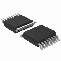
ADT7475ARQZ ON Semiconductor, ADT7475ARQZ Datasheet - Page 34

ADT7475ARQZ
Manufacturer Part Number
ADT7475ARQZ
Description
IC REMOTE THERMAL CTRLR 16-QSOP
Manufacturer
ON Semiconductor
Series
dBCool®r
Datasheet
1.ADT7475ARQZ.pdf
(58 pages)
Specifications of ADT7475ARQZ
Function
Fan Control, Temp Monitor
Topology
ADC, Comparator, Fan Speed Counter, Multiplexer, Register Bank
Sensor Type
External & Internal
Sensing Temperature
-40°C ~ 125°C, External Sensor
Output Type
SMBus™
Output Alarm
No
Output Fan
Yes
Voltage - Supply
3 V ~ 3.6 V
Operating Temperature
-40°C ~ 125°C
Mounting Type
Surface Mount
Package / Case
16-QSOP
Full Temp Accuracy
+/- 0.5 C
Digital Output - Bus Interface
Serial (3-Wire, 4-Wire)
Maximum Operating Temperature
+ 125 C
Minimum Operating Temperature
- 40 C
Lead Free Status / RoHS Status
Lead free / RoHS Compliant
Available stocks
Company
Part Number
Manufacturer
Quantity
Price
Part Number:
ADT7475ARQZ
Manufacturer:
ADI/亚德诺
Quantity:
20 000
Company:
Part Number:
ADT7475ARQZ-REEL7
Manufacturer:
SANYO
Quantity:
2 970
Part Number:
ADT7475ARQZ-REEL7
Manufacturer:
ADI/亚德诺
Quantity:
20 000
Part Number:
ADT7475ARQZ-RL7
Manufacturer:
ON/安森美
Quantity:
20 000
single temperature measurement channel. For example,
Remote 1 temperature can control PWM1 and PWM2
outputs. If two different fans are used on PWM1 and PWM2,
the fan characteristics can be set up differently. As a result,
Fan 1 driven by PWM1 can have a different PWM
than Fan 2 connected to PWM2. Figure 50 illustrates this as
PWM1
20%, while PWM2
40% duty cycle. Note that both fans turn on at exactly the
same temperature, defined by T
Programming the PWM
minimum PWM duty cycle for each output to be configured
anywhere from 0% to 100%. This allows the minimum
PWM duty cycle to be set in steps of 0.39%.
given by:
Example 1: For a minimum PWM duty cycle of 50%,
Example 2: For a minimum PWM duty cycle of 33%,
PWM
Register 0x64, PWM1 Minimum Duty Cycle = 0x80
(50% default)
Register 0x65, PWM2 Minimum Duty Cycle = 0x80
(50% default)
Register 0x66, PWM3 Minimum Duty Cycle = 0x80
(50% default)
Note on Fan Speed and PWM Duty Cycle
speed in RPM. Running a fan at 33% PWM duty cycle does
not equate to running the fan at 33% speed. Driving a fan at
33% PWM duty cycle actually runs the fan at closer to 50%
of its full speed. This is because fan speed in %RPM
generally relates to the square root of the PWM duty cycle.
More than one PWM output can be controlled from a
The PWM
The value to be programmed into the PWM
The PWM duty cycle does not directly correlate to fan
Figure 50. Operating Two Different Fans from a
Value (decimal) = PWM
Value (decimal) = 50/0.39 = 128 (decimal)
Value = 128 (decimal) or 80 (hex)
Value (decimal) = 33/0.39 = 85 (decimal)
Value = 85 (decimal) or 54 (hex)
MIN
MIN
PWM2
PWM1
Registers
100%
(front fan) turns on at a minimum duty cycle of
MIN
MIN
0%
MIN
Single Temperature Channel
registers are 8−bit registers that allow the
MIN
T
MIN
(rear fan) turns on at a minimum of
MIN
Registers
MIN
PWM2
MIN
/0.39
PWM1
.
TEMPERATURE
MIN
MIN
register is
http://onsemi.com
value
34
Given a PWM square wave as the drive signal, fan speed in
RPM approximates to:
Step 5: PWM
system runs at under the automatic fan speed control loop.
For maximum system acoustic benefit, PWM
as low as possible but should be capable of maintaining the
processor temperature limit at an acceptable level. If the
THERM temperature limit is exceeded, the fans are still
boosted to 100% for fail−safe cooling.
default value of all PWM
Programming the PWM
maximum PWM duty cycle for each output to be configured
anywhere from 0% to 100%. This allows the maximum
PWM duty cycle to be set in steps of 0.39%.
is given by:
Example 1: For a maximum PWM duty cycle of 50%,
Example 2: For a minimum PWM duty cycle of 75%,
PWM
Register 0x38, PWM1 Maximum DutyCycle = 0xFF
(100% default)
Register 0x39, PWM2 Maximum Duty Cycle = 0xFF
(100% default)
Register 0x3A, PWM3 Maximum Duty Cycle = 0xFF
(100% default)
Figure 51. PWM
PWM
There is a PWM
The PWM
The value to be programmed into the PWM
Value (decimal) = PWM
Value (decimal) − 50/0.39 = 128 (decimal)
Value = 128 (decimal) or 80 (hex)
Value (decimal) = 75/0.39 = 192 (decimal)
Value = 192 (decimal) or C0 (hex)
MAX
Cycle Below the THERM Temperature Limit
% fanspeed + PWM duty cycle
PWM
MAX
PWM
Registers
100%
MAX
MIN
0%
MAX
is the maximum duty cycle that each fan in the
MAX
MAX
registers are 8−bit registers that allow the
for PWM (Fan) Outputs
MAX
T
Determines Maximum PWM Duty
MIN
MAX
MAX
limit for each fan channel. The
MAX
Registers
registers is 0xFF.
/0.39
TEMPERATURE
10
MAX
MAX
should be
register
(eq. 4)


