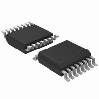
ADT7475ARQZ ON Semiconductor, ADT7475ARQZ Datasheet - Page 35

ADT7475ARQZ
Manufacturer Part Number
ADT7475ARQZ
Description
IC REMOTE THERMAL CTRLR 16-QSOP
Manufacturer
ON Semiconductor
Series
dBCool®r
Datasheet
1.ADT7475ARQZ.pdf
(58 pages)
Specifications of ADT7475ARQZ
Function
Fan Control, Temp Monitor
Topology
ADC, Comparator, Fan Speed Counter, Multiplexer, Register Bank
Sensor Type
External & Internal
Sensing Temperature
-40°C ~ 125°C, External Sensor
Output Type
SMBus™
Output Alarm
No
Output Fan
Yes
Voltage - Supply
3 V ~ 3.6 V
Operating Temperature
-40°C ~ 125°C
Mounting Type
Surface Mount
Package / Case
16-QSOP
Full Temp Accuracy
+/- 0.5 C
Digital Output - Bus Interface
Serial (3-Wire, 4-Wire)
Maximum Operating Temperature
+ 125 C
Minimum Operating Temperature
- 40 C
Lead Free Status / RoHS Status
Lead free / RoHS Compliant
Available stocks
Company
Part Number
Manufacturer
Quantity
Price
Part Number:
ADT7475ARQZ
Manufacturer:
ADI/亚德诺
Quantity:
20 000
Company:
Part Number:
ADT7475ARQZ-REEL7
Manufacturer:
SANYO
Quantity:
2 970
Part Number:
ADT7475ARQZ-REEL7
Manufacturer:
ADI/亚德诺
Quantity:
20 000
Part Number:
ADT7475ARQZ-RL7
Manufacturer:
ON/安森美
Quantity:
20 000
Step 6: T
fan control occurs once the programmed T
has been exceeded. T
between PWM
changes linearly. Otherwise stated, it is the line drawn
between the T
/PWM 100% intersection points.
also changes.
T
smaller temperature change.
Figure 53. Adjusting PWM
RANGE
Figure 52. T
T
The T
As PWM
As T
RANGE
1. Determine the maximum operating temperature for
2. Determine, experimentally, the fan speed (PWM
3. Determine the slope of the required control loop to
4. Using the ADT7475 evaluation software,
that channel (for example, 70°C).
duty cycle value) that does not exceed the
temperature at the worst−case operating points.
(For example, 70°C is reached when the fans are
running at 50% PWM duty cycle.)
meet these requirements.
graphically program and visualize this
functionality.
RANGE
PWM
RANGE
100%
gets smaller, the fans reach 100% speed with a
RANGE
50%
33%
100%
0%
is the range of temperature over which automatic
MIN
MIN
0%
RANGE
MIN
MIN
is determined by the following procedure:
is changed, the automatic fan control slope
is changed, the slope also changes. As
for Temperature Channels
Fan Control Slope
/PWM
and 100% PWM where the fan speed
T
MIN
Parameter Affects Cooling Slope
T
MIN
RANGE
MIN
MIN
305C
and the (T
is the temperature range
Changes the Automatic
T
RANGE
TEMPERATURE
MIN
MIN
temperature
+ T
RANGE
http://onsemi.com
)
35
Selecting T
channel: Remote 1, local, and Remote 2 temperatures. Bits
[7:4] (RANGE) of Register 0x5F to Register 0x61 define the
T
Figure 54. Increasing T
Table 10. Selecting a T
RANGE
Figure 55. Changing PWM
1. Register 0x5F configures Remote 1 T
The T
configures local T
T
Bits [7:4] (Note 1)
RANGE
RANGE
value for each temperature channel.
100%
100%
PWM
MAX
10%
10%
0%
0%
.
0000
0001
0010
0011
0100
0101
0110
1000
1001
1010
1011
1100
1101
0111
1110
1111
RANGE
T
MIN – HYST
T
MIN – HYST
value can be selected for each temperature
RANGE
T
MIN
AFC Slope
RANGE
RANGE
; Register 0x61 configures Remote 2
T
305C
MAX
RANGE
405C
Value
Changes the AFC Slope
455C
Does Not Change the
545C
T
RANGE
32 (default)
RANGE
13.33
26.67
53.33
3.33
6.67
2.5
10
16
20
40
80
2
4
5
8
; Register 0x60
(5C)


