TLP181 Toshiba, TLP181 Datasheet - Page 57
TLP181
Manufacturer Part Number
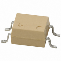
TLP181
Description
PHOTOCOUPLER TRANS-OUT 4-SMD
Manufacturer
Toshiba
Specifications of TLP181
Number Of Channels
1
Input Type
DC
Voltage - Isolation
3750Vrms
Current Transfer Ratio (min)
50% @ 5mA
Current Transfer Ratio (max)
600% @ 5mA
Voltage - Output
80V
Current - Output / Channel
50mA
Current - Dc Forward (if)
50mA
Vce Saturation (max)
400mV
Output Type
Transistor
Mounting Type
Surface Mount
Package / Case
4-SMD
Lead Free Status / RoHS Status
Contains lead / RoHS non-compliant
Available stocks
Company
Part Number
Manufacturer
Quantity
Price
Company:

Part Number:
TLP181
Manufacturer:
TOSHIBA
Quantity:
1 500
Company:
Part Number:
TLP181
Manufacturer:
TOSHIBA
Quantity:
184
Part Number:
TLP181
Manufacturer:
TOSHIBA/东芝
Quantity:
20 000
Part Number:
TLP181 GR
Manufacturer:
TOSHIBA/东芝
Quantity:
20 000
Part Number:
TLP181(BL
Manufacturer:
TOSHIBA/东芝
Quantity:
20 000
Part Number:
TLP181(BL-TPL
Manufacturer:
TOSHIBA/东芝
Quantity:
20 000
Part Number:
TLP181(BL-TPL)
Manufacturer:
TOSHIBA/东芝
Quantity:
20 000
Company:
Part Number:
TLP181(F)
Manufacturer:
TOSHIBA
Quantity:
1 467
Company:
Part Number:
TLP181(GB-TPL
Manufacturer:
TOS
Quantity:
6 022


When using a soldering iron or medium infrared ray/hot air reflow,
avoid a rise in device temperature as much as possible by
observing the following conditions.
1.1 )
1.2 )
1.3 )
2
1. Soldering
a. Solder once within 10 seconds for a lead temperature of
b. Solder once within 3 seconds for a lead temperature of up
a. Complete the infrared ray/hot air reflow process at once
d. Precautions for heating
Using a soldering iron
Using medium infrared ray/hot air reflow
b. Example of temperature profile of lead (Pb) solder
c. Example of temperature profile of lead (Pb)-free solder
The thermal shock of dip soldering increases thermal stress
on devices. To avoid stress, the use of a soldering iron or
medium infrared ray/hot air reflow is recommended. If you
want to use dip soldering, contact your nearest Toshiba
sales representative.
Dip soldering (flow soldering)
up to 260°C.
to 350°C.
within 30 seconds at a package surface temperature
between 210°C and 240°C.
The profile below shows only the typical temperature profile
and conditions, which might not apply to all Toshiba
photocouplers. Temperature profiles and conditions may
differ from product to product. Refer to the relevant technical
datasheets and databooks when mounting a device.
Keeping packages at high temperature for a long period of
time can degrade the quality and reliability of devices.
Soldering time has to be kept as short as possible to
avoid a rise in package temperature.
When using a halogen lamp or infrared heater, avoid
direct irradiation of packages, since this may cause a rise
in package temperature.
Board Assembly Considerations
Example of temperature profile of lead (Pb)-free solder
Example of temperature profile of lead (Pb) solder
(°C)
(°C)
260
230
190
180
240
210
150
60 to 120 seconds
60 to 90 seconds
30 seconds or less
30 to 50 seconds
Time
Time
57
●When cleaning circuit boards to remove flux, make sure that
●Washing devices with water will not cause any problems.
●Do not rub device markings with a brush or with your hand
●Dip cleaning, shower cleaning and steam cleaning processes
●If a device package allows ultrasonic cleaning, keep the
■ The following ultrasonic cleaning conditions
are recommended.
Examples of Alternative Cleaning Agents
Frequency: 27 kHz to 29 kHz
Ultrasonic output power: 300 W or less (0.25 W/cm
Cleaning time: 30 seconds or less
Suspend the circuit board in the solvent bath during ultrasonic
cleaning in such a way that the ultrasonic vibrator does not come
into direct contact with the circuit board or the device.
Conventional cleaning solvents that contain freon are not
recommended due to its adverse effection the earth’s ozone layer.
Alternative freon-free products are available on the market. Some
of these alternative cleaning agents are listed in the table below.
Contact Toshiba or a Toshiba distributor regarding cleaning
conditions and other relevant information for each product type.
no residual reactive ions such as sodium(Na
ions remain. Note that organic solvents react with water to
generate hydrogen chloride and other corrosive gases, which
can degrade device performance.
However, make sure that no reactive ions such as
sodium(Na
sure to dry devices sufficiently after washing.
during cleaning or while the devices are still wet from the
cleaning agent. Doing so can rub off the markings.
all involve the chemical action of a solvent. Use only
recommended solvents for these cleaning methods. When
immersing devices in a solvent or steam bath, make sure
that the temperature of the liquid is 50°C or below and that
the circuit board is removed from the bath within one minute.
duration of ultrasonic cleaning as short as possible, since
long hours of ultrasonic cleaning degrade the adhesion
between the mold resin and the frame material.
2. Flux Cleaning
Technocare
Asahi Clean
Clean Through
Pine Alpha
+
) or chloride(Cl
FRW-1, FRW-17,
FRV-100
AK-225AES
750H
ST-100S,
ST-100SX
–
) ions are left as residue. Also, be
GE Toshiba Silicon
Asahi Glass Co., Ltd
Kao Co., Ltd.
Arakawa Chemical Co., Ltd.
+
) or chloride(Cl
2
or less)
–
)
Related parts for TLP181
Image
Part Number
Description
Manufacturer
Datasheet
Request
R

Part Number:
Description:
Toshiba Semiconductor [TOSHIBA IGBT Module Silicon N Channel IGBT]
Manufacturer:
TOSHIBA Semiconductor CORPORATION
Datasheet:
Part Number:
Description:
TOSHIBA GTR MODULE SILICON NPN TRIPLE DIFFUSED TYPE
Manufacturer:
TOSHIBA Semiconductor CORPORATION
Datasheet:
Part Number:
Description:
TOSHIBA GTR Module Silicon N Channel IGBT
Manufacturer:
TOSHIBA Semiconductor CORPORATION
Datasheet:
Part Number:
Description:
TOSHIBA Intelligent Power Module Silicon N Channel IGBT
Manufacturer:
TOSHIBA Semiconductor CORPORATION
Datasheet:
Part Number:
Description:
TOSHIBA INTELLIGENT POWER MODULE SILICON N CHANNEL LGBT
Manufacturer:
TOSHIBA Semiconductor CORPORATION
Datasheet:
Part Number:
Description:
TOSHIBA IGBT Module Silicon N Channel IGBT
Manufacturer:
TOSHIBA Semiconductor CORPORATION
Datasheet:
Part Number:
Description:
TOSHIBA GTR MODULE SILICON N−CHANNEL IGBT
Manufacturer:
TOSHIBA Semiconductor CORPORATION
Datasheet:
Part Number:
Description:
TOSHIBA Intelligent Power Module Silicon N Channel IGBT
Manufacturer:
TOSHIBA Semiconductor CORPORATION
Datasheet:
Part Number:
Description:
TOSHIBA GTR Module Silicon N Channel IGBT
Manufacturer:
TOSHIBA Semiconductor CORPORATION
Datasheet:
Part Number:
Description:
TOSHIBA INTELLIGENT POWER MODULE
Manufacturer:
TOSHIBA Semiconductor CORPORATION
Datasheet:
Part Number:
Description:
TOSHIBA Intelligent Power Module Silicon N Channel IGBT
Manufacturer:
TOSHIBA Semiconductor CORPORATION
Datasheet:
Part Number:
Description:
TOSHIBA Intelligent Power Module Silicon N Channel IGBT
Manufacturer:
TOSHIBA Semiconductor CORPORATION
Datasheet:
Part Number:
Description:
TOSHIBA IGBT Module Silicon N Channel IGBT
Manufacturer:
TOSHIBA Semiconductor CORPORATION
Datasheet:
Part Number:
Description:
TOSHIBA Intelligent Power Module Silicon N Channel IGBT
Manufacturer:
TOSHIBA Semiconductor CORPORATION
Datasheet:
Part Number:
Description:
Toshiba Semiconductor [SILICON N CHANNEL 1GBT]
Manufacturer:
TOSHIBA Semiconductor CORPORATION
Datasheet: