TLP181 Toshiba, TLP181 Datasheet - Page 64
TLP181
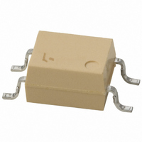
Manufacturer Part Number
TLP181
Description
PHOTOCOUPLER TRANS-OUT 4-SMD
Manufacturer
Toshiba
Specifications of TLP181
Number Of Channels
1
Input Type
DC
Voltage - Isolation
3750Vrms
Current Transfer Ratio (min)
50% @ 5mA
Current Transfer Ratio (max)
600% @ 5mA
Voltage - Output
80V
Current - Output / Channel
50mA
Current - Dc Forward (if)
50mA
Vce Saturation (max)
400mV
Output Type
Transistor
Mounting Type
Surface Mount
Package / Case
4-SMD
Lead Free Status / RoHS Status
Contains lead / RoHS non-compliant
Available stocks
Company
Part Number
Manufacturer
Quantity
Price
Company:

Part Number:
TLP181
Manufacturer:
TOSHIBA
Quantity:
1 500
Company:
Part Number:
TLP181
Manufacturer:
TOSHIBA
Quantity:
184
Part Number:
TLP181
Manufacturer:
TOSHIBA/东芝
Quantity:
20 000
Part Number:
TLP181 GR
Manufacturer:
TOSHIBA/东芝
Quantity:
20 000
Part Number:
TLP181(BL
Manufacturer:
TOSHIBA/东芝
Quantity:
20 000
Part Number:
TLP181(BL-TPL
Manufacturer:
TOSHIBA/东芝
Quantity:
20 000
Part Number:
TLP181(BL-TPL)
Manufacturer:
TOSHIBA/东芝
Quantity:
20 000
Company:
Part Number:
TLP181(F)
Manufacturer:
TOSHIBA
Quantity:
1 467
Company:
Part Number:
TLP181(GB-TPL
Manufacturer:
TOS
Quantity:
6 022


9
For example, let's calculate the operating life of the GaAs LED, based on the data shown on page 60.
Here is an example of how to read an operating life, assuming that the ambient temperature (Ta) is 40°C and that the failure
criterion is a 30% decrease in light output.
Suppose that the initial LED current, IF, is 20 mA. Since the horizontal axis of the failure criteria graph is the reciprocal of absolute
temperature, it is necessary to convert the ambient temperature (Ta) to the reciprocal of absolute temperature (T):
The graph shows the projected lifetimes for F50% and F0.1% cumulative failure probabilities in solid and dashed lines respectively.
Normally, it is recommended to use F0.1% lines.
As X = 3.19, its intersection with the IF = 20 mA line for F0.1% is approximately 80,000 hours. (This figure is for reference only.)
You can also estimate the projected operating life from the projected light output degradation data.
Reading the Projected LED Operating Life Graph
Device Degradation
T =
Ta + 273.15
1
=
10000000
1000000
100000
40 + 273.15
80000
10000
1000
140
120
100
100
80
70
60
40
20
0
227
2.0
1
1
–30%
I
I
I
I
I
F
F
F
F
F
150
Failure criteria for light output degradation Δ P O < –30%
= 10mA
= 20mA
= 30mA
= 40mA
= 50mA
10
3.19 × 10
100 85
Test conditions: I
3.0
60
3.19
100
−3
40
Test time (h)
64
F
25
= 20 mA, Ta = 40°C
1000
0
4.0
I
I
I
I
I
−20
F
F
F
F
F
= 10mA
= 20mA
= 30mA
= 40mA
= 50mA
Projected F50%
operating life
Projected F0.1%
operating life
Ambient Temperature (°C)
10000
X-3σ
−50
1/K(×10
X
80000
100000
−73
5.0
–3
)
Related parts for TLP181
Image
Part Number
Description
Manufacturer
Datasheet
Request
R

Part Number:
Description:
Toshiba Semiconductor [TOSHIBA IGBT Module Silicon N Channel IGBT]
Manufacturer:
TOSHIBA Semiconductor CORPORATION
Datasheet:
Part Number:
Description:
TOSHIBA GTR MODULE SILICON NPN TRIPLE DIFFUSED TYPE
Manufacturer:
TOSHIBA Semiconductor CORPORATION
Datasheet:
Part Number:
Description:
TOSHIBA GTR Module Silicon N Channel IGBT
Manufacturer:
TOSHIBA Semiconductor CORPORATION
Datasheet:
Part Number:
Description:
TOSHIBA Intelligent Power Module Silicon N Channel IGBT
Manufacturer:
TOSHIBA Semiconductor CORPORATION
Datasheet:
Part Number:
Description:
TOSHIBA INTELLIGENT POWER MODULE SILICON N CHANNEL LGBT
Manufacturer:
TOSHIBA Semiconductor CORPORATION
Datasheet:
Part Number:
Description:
TOSHIBA IGBT Module Silicon N Channel IGBT
Manufacturer:
TOSHIBA Semiconductor CORPORATION
Datasheet:
Part Number:
Description:
TOSHIBA GTR MODULE SILICON N−CHANNEL IGBT
Manufacturer:
TOSHIBA Semiconductor CORPORATION
Datasheet:
Part Number:
Description:
TOSHIBA Intelligent Power Module Silicon N Channel IGBT
Manufacturer:
TOSHIBA Semiconductor CORPORATION
Datasheet:
Part Number:
Description:
TOSHIBA GTR Module Silicon N Channel IGBT
Manufacturer:
TOSHIBA Semiconductor CORPORATION
Datasheet:
Part Number:
Description:
TOSHIBA INTELLIGENT POWER MODULE
Manufacturer:
TOSHIBA Semiconductor CORPORATION
Datasheet:
Part Number:
Description:
TOSHIBA Intelligent Power Module Silicon N Channel IGBT
Manufacturer:
TOSHIBA Semiconductor CORPORATION
Datasheet:
Part Number:
Description:
TOSHIBA Intelligent Power Module Silicon N Channel IGBT
Manufacturer:
TOSHIBA Semiconductor CORPORATION
Datasheet:
Part Number:
Description:
TOSHIBA IGBT Module Silicon N Channel IGBT
Manufacturer:
TOSHIBA Semiconductor CORPORATION
Datasheet:
Part Number:
Description:
TOSHIBA Intelligent Power Module Silicon N Channel IGBT
Manufacturer:
TOSHIBA Semiconductor CORPORATION
Datasheet:
Part Number:
Description:
Toshiba Semiconductor [SILICON N CHANNEL 1GBT]
Manufacturer:
TOSHIBA Semiconductor CORPORATION
Datasheet: