DEMO9S08LC60 Freescale Semiconductor, DEMO9S08LC60 Datasheet - Page 136
DEMO9S08LC60
Manufacturer Part Number
DEMO9S08LC60
Description
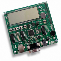
BOARD DEMO FOR 9S08LC60
Manufacturer
Freescale Semiconductor
Type
MCUr
Datasheets
1.DEMO9S08LC60.pdf
(360 pages)
2.DEMO9S08LC60.pdf
(32 pages)
3.DEMO9S08LC60.pdf
(2 pages)
Specifications of DEMO9S08LC60
Contents
Evaluation Board
Processor To Be Evaluated
MC9S08LC60
Interface Type
RS-232, USB
Silicon Manufacturer
Freescale
Core Architecture
HCS08
Core Sub-architecture
HCS08
Silicon Core Number
MC9S08
Silicon Family Name
S08LC
Rohs Compliant
Yes
For Use With/related Products
MC9S08LC60
Lead Free Status / RoHS Status
Lead free / RoHS Compliant


Chapter 9 Liquid Crystal Display Driver (S08LCDV1)
9.3.8
Read: anytime. The LCDCLR bit always reads zero.
Write: anytime.
136
BRATE[2:0]
BLKMODE
LCDDRMS
Reset
BLINK
LCDIF
Field
Field
2:0
7
3
7
3
W
R
LCDIF
LCD Command and Status Register (LCDCMD)
Blink Command — Starts or stops LCD module blinking.The blink command takes effect at the beginning of the
next LCD frame cycle.
0 Disables blinking.
1 Starts blinking at blinking frequency specified by
Blink Mode Select — Configures whether to blink either individual LCD segments or the entire LCD panel
depending on the state of the BLKMODE bit.BLINK must be enabled; if BLINK = 0, this bit has no effect.
0 Blink only individual LCD segments as specified by the LCDRAM register banks.
1 Blink all LCD segments regardless of contents of the LCDRAM register banks.
Blink Rate Configuration— Selects the frequency at which the LCD display blinks when the BLINK is asserted.
Equation 9-4
Equation 9-4
LCD module blink rate calculations are provided in 9.4.3.2/p.150.
LCD Interrupt Flag — LCDIF indicates that an interrupt condition has occurred. To clear the interrupt, read
LCDCMD register and then write a 1 to LCDIF.
0 interrupt condition has not occurred.
1 interrupt condition has occurred.
LCD Module Data Register Mode Select — The LCDRAM registers provide access to two different register
groups. Access to each register group is controlled by the state of the LCDDRMS bit.
0 Selects the LCDRAM registers to access registers that control the on/off state for LCD segments.
1 Selects the LCDRAM registers to access registers that control the blink enable/disable state for LCD
0
7
segments.
Unimplemented or Reserved
LCD module blink rate
shows how BRATE[2:0] bit field is used in the
provides an expression for the LCD waveform base clock
0
0
6
MC9S08LC60 Series Data Sheet: Technical Data, Rev. 4
Figure 9-9. LCD Command Register (LCDCMD)
Table 9-11. LCDBCTL Field Descriptions
Table 9-12. LCDCMD Field Descriptions
0
0
5
=
LCD waveform base clock
2
0
0
4
(5+ BRATE[2:0])
Description
Description
LCD
LCDDRMS
blink rate calculation (see
LCD
3
0
blink rate calculation.
0
0
2
Equation
LCDCLR
Freescale Semiconductor
0
0
1
9-4).
Eqn. 9-4
BLANK
0
0
Related parts for DEMO9S08LC60
Image
Part Number
Description
Manufacturer
Datasheet
Request
R

Part Number:
Description:
Manufacturer:
Freescale Semiconductor, Inc
Datasheet:
Part Number:
Description:
Manufacturer:
Freescale Semiconductor, Inc
Datasheet:
Part Number:
Description:
Manufacturer:
Freescale Semiconductor, Inc
Datasheet:
Part Number:
Description:
Manufacturer:
Freescale Semiconductor, Inc
Datasheet:
Part Number:
Description:
Manufacturer:
Freescale Semiconductor, Inc
Datasheet:
Part Number:
Description:
Manufacturer:
Freescale Semiconductor, Inc
Datasheet:
Part Number:
Description:
Manufacturer:
Freescale Semiconductor, Inc
Datasheet:
Part Number:
Description:
Manufacturer:
Freescale Semiconductor, Inc
Datasheet:
Part Number:
Description:
Manufacturer:
Freescale Semiconductor, Inc
Datasheet:
Part Number:
Description:
Manufacturer:
Freescale Semiconductor, Inc
Datasheet:
Part Number:
Description:
Manufacturer:
Freescale Semiconductor, Inc
Datasheet:
Part Number:
Description:
Manufacturer:
Freescale Semiconductor, Inc
Datasheet:
Part Number:
Description:
Manufacturer:
Freescale Semiconductor, Inc
Datasheet:
Part Number:
Description:
Manufacturer:
Freescale Semiconductor, Inc
Datasheet:
Part Number:
Description:
Manufacturer:
Freescale Semiconductor, Inc
Datasheet: