DEMO9S08LC60 Freescale Semiconductor, DEMO9S08LC60 Datasheet - Page 268
DEMO9S08LC60
Manufacturer Part Number
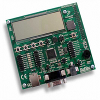
DEMO9S08LC60
Description
BOARD DEMO FOR 9S08LC60
Manufacturer
Freescale Semiconductor
Type
MCUr
Datasheets
1.DEMO9S08LC60.pdf
(360 pages)
2.DEMO9S08LC60.pdf
(32 pages)
3.DEMO9S08LC60.pdf
(2 pages)
Specifications of DEMO9S08LC60
Contents
Evaluation Board
Processor To Be Evaluated
MC9S08LC60
Interface Type
RS-232, USB
Silicon Manufacturer
Freescale
Core Architecture
HCS08
Core Sub-architecture
HCS08
Silicon Core Number
MC9S08
Silicon Family Name
S08LC
Rohs Compliant
Yes
For Use With/related Products
MC9S08LC60
Lead Free Status / RoHS Status
Lead free / RoHS Compliant


Chapter 15 Analog-to-Digital Converter (S08ADC12V1)
15.1.1.2 Alternate Clock
The ADC is capable of performing conversions using the MCU bus clock, the bus clock divided by two,
or the local asynchronous clock (ADACK) within the module. The alternate clock, ALTCLK, input for the
MC9S08LC60/36/20 MCU devices is not implemented.
15.1.1.3 Hardware Trigger
The ADC hardware trigger, ADHWT, is output from the real-time interrupt (RTI) counter. The RTI counter
can be clocked by either ICGERCLK or a nominal 1-kHz clock source within the RTI block.
The period of the RTI is determined by the input clock frequency and the RTIS bits. The RTI counter is a
free running counter that generates an overflow at the RTI rate determined by the RTIS bits. When the ADC
hardware trigger is enabled, a conversion is initiated upon a RTI counter overflow.
The RTI can be configured to cause a hardware trigger in MCU run, wait, and stop3.
15.1.1.4 Analog Pin Enables
The ADC on MC9S08LC60/36/20 MCU devices contains only one analog pin enable registers, APCTL1.
15.1.1.5 Temperature Sensor
To use the on-chip temperature sensor, the user must perform the following:
268
1. Configure ADC for long sample with a maximum of 1-MHz clock.
2. Convert the bandgap voltage reference channel (AD27).
3. Convert the temperature sensor channel (AD26).
4. To improve accuracy, the user should calibrate the bandgap voltage reference and temperature
By converting the digital value of the bandgap voltage reference channel using the value of VBG,
the user can determine V
By using the calculated value of V
Equation 15-1
V
0.0017 is the uncalibrated voltage versus temperature slope in V/˚C. Uncalibrated accuracy of the
temperature sensor is approximately ± 12˚C, using
sensor.
— Calibrating at 25˚C will improve accuracy to 4.5˚C.
— Calibration at three temperature points (–40˚C, 25˚C, and 125˚C) will improve accuracy to
DD
± 2.5˚C. After calibration has been completed, the user must calculate the slope for both hot
and cold. In application code, the user would then calculate the temperature using
Equation 15-1
determining whether the temperature is above or below 25˚C, the user can recalculate the
temperature using either the hot or cold slope value obtained during calibration.
= 3.0 V, Temp = 25˚C, using the ADC at f
provides an approximate transfer function of the on-chip temperature sensor for:
and then determine whether the temperature is above or below 25˚C. After
MC9S08LC60 Series Data Sheet: Technical Data, Rev. 4
TempC = (V
DD
. For value of bandgap voltage, see Section A.5, “DC Characteristics”.
temp
DD
, convert the digital value of AD26 into a voltage, V
– 0.7013) ÷ (0.0017)
ADCK
Equation
= 1.0 MHz, and configured for long sample.
15-1.
Freescale Semiconductor
Eqn. 15-1
temp
Related parts for DEMO9S08LC60
Image
Part Number
Description
Manufacturer
Datasheet
Request
R

Part Number:
Description:
Manufacturer:
Freescale Semiconductor, Inc
Datasheet:
Part Number:
Description:
Manufacturer:
Freescale Semiconductor, Inc
Datasheet:
Part Number:
Description:
Manufacturer:
Freescale Semiconductor, Inc
Datasheet:
Part Number:
Description:
Manufacturer:
Freescale Semiconductor, Inc
Datasheet:
Part Number:
Description:
Manufacturer:
Freescale Semiconductor, Inc
Datasheet:
Part Number:
Description:
Manufacturer:
Freescale Semiconductor, Inc
Datasheet:
Part Number:
Description:
Manufacturer:
Freescale Semiconductor, Inc
Datasheet:
Part Number:
Description:
Manufacturer:
Freescale Semiconductor, Inc
Datasheet:
Part Number:
Description:
Manufacturer:
Freescale Semiconductor, Inc
Datasheet:
Part Number:
Description:
Manufacturer:
Freescale Semiconductor, Inc
Datasheet:
Part Number:
Description:
Manufacturer:
Freescale Semiconductor, Inc
Datasheet:
Part Number:
Description:
Manufacturer:
Freescale Semiconductor, Inc
Datasheet:
Part Number:
Description:
Manufacturer:
Freescale Semiconductor, Inc
Datasheet:
Part Number:
Description:
Manufacturer:
Freescale Semiconductor, Inc
Datasheet:
Part Number:
Description:
Manufacturer:
Freescale Semiconductor, Inc
Datasheet: