DEMO9S08LC60 Freescale Semiconductor, DEMO9S08LC60 Datasheet - Page 285
DEMO9S08LC60
Manufacturer Part Number
DEMO9S08LC60
Description
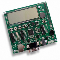
BOARD DEMO FOR 9S08LC60
Manufacturer
Freescale Semiconductor
Type
MCUr
Datasheets
1.DEMO9S08LC60.pdf
(360 pages)
2.DEMO9S08LC60.pdf
(32 pages)
3.DEMO9S08LC60.pdf
(2 pages)
Specifications of DEMO9S08LC60
Contents
Evaluation Board
Processor To Be Evaluated
MC9S08LC60
Interface Type
RS-232, USB
Silicon Manufacturer
Freescale
Core Architecture
HCS08
Core Sub-architecture
HCS08
Silicon Core Number
MC9S08
Silicon Family Name
S08LC
Rohs Compliant
Yes
For Use With/related Products
MC9S08LC60
Lead Free Status / RoHS Status
Lead free / RoHS Compliant


15.4.5
The compare function can be configured to check for either an upper limit or lower limit. After the input
is sampled and converted, the result is added to the two’s complement of the compare value (ADCCVH
and ADCCVL). When comparing to an upper limit (ACFGT = 1), if the result is greater-than or equal-to
the compare value, COCO is set. When comparing to a lower limit (ACFGT = 0), if the result is less than
the compare value, COCO is set. The value generated by the addition of the conversion result and the two’s
complement of the compare value is transferred to ADCRH and ADCRL.
Upon completion of a conversion while the compare function is enabled, if the compare condition is not
true, COCO is not set and no data is transferred to the result registers. An ADC interrupt is generated upon
the setting of COCO if the ADC interrupt is enabled (AIEN = 1).
15.4.6
The WAIT instruction puts the MCU in a lower power-consumption standby mode from which recovery
is very fast because the clock sources remain active. If a conversion is in progress when the MCU enters
wait mode, it continues until completion. Conversions can be initiated while the MCU is in wait mode by
means of the hardware trigger or if continuous conversions are enabled.
The bus clock, bus clock divided by two, and ADACK are available as conversion clock sources while in
wait mode. The use of ALTCLK as the conversion clock source in wait is dependent on the definition of
ALTCLK for this MCU. Consult the module introduction for information on ALTCLK specific to this
MCU.
A conversion complete event sets the COCO and generates an ADC interrupt to wake the MCU from wait
mode if the ADC interrupt is enabled (AIEN = 1).
15.4.7
The STOP instruction is used to put the MCU in a low power-consumption standby mode during which
most or all clock sources on the MCU are disabled.
15.4.7.1
If the asynchronous clock, ADACK, is not selected as the conversion clock, executing a STOP instruction
aborts the current conversion and places the ADC in its idle state. The contents of ADCRH and ADCRL
are unaffected by stop3 mode. After exiting from stop3 mode, a software or hardware trigger is required
to resume conversions.
Freescale Semiconductor
Automatic Compare Function
MCU Wait Mode Operation
MCU Stop3 Mode Operation
Stop3 Mode With ADACK Disabled
The compare function can be used to monitor the voltage on a channel while
the MCU is in either wait or stop3 mode. The ADC interrupt will wake the
MCU when the compare condition is met.
MC9S08LC60 Series Data Sheet: Technical Data, Rev. 4
NOTE
Chapter 15 Analog-to-Digital Converter (S08ADC12V1)
285
Related parts for DEMO9S08LC60
Image
Part Number
Description
Manufacturer
Datasheet
Request
R

Part Number:
Description:
Manufacturer:
Freescale Semiconductor, Inc
Datasheet:
Part Number:
Description:
Manufacturer:
Freescale Semiconductor, Inc
Datasheet:
Part Number:
Description:
Manufacturer:
Freescale Semiconductor, Inc
Datasheet:
Part Number:
Description:
Manufacturer:
Freescale Semiconductor, Inc
Datasheet:
Part Number:
Description:
Manufacturer:
Freescale Semiconductor, Inc
Datasheet:
Part Number:
Description:
Manufacturer:
Freescale Semiconductor, Inc
Datasheet:
Part Number:
Description:
Manufacturer:
Freescale Semiconductor, Inc
Datasheet:
Part Number:
Description:
Manufacturer:
Freescale Semiconductor, Inc
Datasheet:
Part Number:
Description:
Manufacturer:
Freescale Semiconductor, Inc
Datasheet:
Part Number:
Description:
Manufacturer:
Freescale Semiconductor, Inc
Datasheet:
Part Number:
Description:
Manufacturer:
Freescale Semiconductor, Inc
Datasheet:
Part Number:
Description:
Manufacturer:
Freescale Semiconductor, Inc
Datasheet:
Part Number:
Description:
Manufacturer:
Freescale Semiconductor, Inc
Datasheet:
Part Number:
Description:
Manufacturer:
Freescale Semiconductor, Inc
Datasheet:
Part Number:
Description:
Manufacturer:
Freescale Semiconductor, Inc
Datasheet: