DEMO9S08LC60 Freescale Semiconductor, DEMO9S08LC60 Datasheet - Page 138
DEMO9S08LC60
Manufacturer Part Number
DEMO9S08LC60
Description
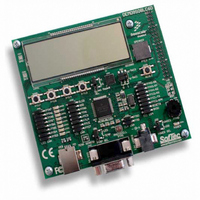
BOARD DEMO FOR 9S08LC60
Manufacturer
Freescale Semiconductor
Type
MCUr
Datasheets
1.DEMO9S08LC60.pdf
(360 pages)
2.DEMO9S08LC60.pdf
(32 pages)
3.DEMO9S08LC60.pdf
(2 pages)
Specifications of DEMO9S08LC60
Contents
Evaluation Board
Processor To Be Evaluated
MC9S08LC60
Interface Type
RS-232, USB
Silicon Manufacturer
Freescale
Core Architecture
HCS08
Core Sub-architecture
HCS08
Silicon Core Number
MC9S08
Silicon Family Name
S08LC
Rohs Compliant
Yes
For Use With/related Products
MC9S08LC60
Lead Free Status / RoHS Status
Lead free / RoHS Compliant


Chapter 9 Liquid Crystal Display Driver (S08LCDV1)
9.4.1
The LCD module driver has three modes of operation:
Note all modes are 1/3 bias. These modes of operation are described in more detail in the following
sections.
9.4.1.1
The duty cycle indicates the number of LCD panel segments capable of being driven by each individual
frontplane output driver. Depending on the duty cycle, the LCD waveform drive can be categorized as
either static or multiplex.
In static driving method, the LCD is driven with two square waveforms. The static driving method is the
most basic method to drive an LCD panel, but, because each frontplace driver can drive only one LCD
segment, static driving limits the number of LCD segments that can be driven. In static mode, only one
backplane is required.
In multiplex mode, the LCD waveforms are multi-level and depend on the bias mode. Multiplex mode,
depending on the number of backplanes, can drive multiple LCD segments with a single frontplane driver.
Multiplex mode is effective in reducing the number of driver circuits and the number of connections to
LCD segments. For multiplex mode operation, at least two backplane drivers are needed. The LCD module
is optimized for multiplex mode.
The duty cycle indicates the amount of time the LCD panel segment is energized during each LCD module
frame cycle. The denominator of the duty cycle indicates the number of backplanes that are being used to
drive an LCD panel. Therefore, the available duty cycle options for the LCD module are 1/2, 1/3, and 1/4.
The duty cycle is configured using the DUTY[1:0] bit field in the LCDCR0 register as shown in
Table
138
•
•
•
9-13.
1/2 duty (2 backplanes), 1/3 bias (4 voltage levels)
1/3 duty (3 backplanes), 1/3 bias (4 voltage levels)
1/4 duty (4 backplanes), 1/3 bias (4 voltage levels)
LCD Driver Description
LCD Duty Cycle
Reserved
Duty
1/2
1/3
1/4
MC9S08LC60 Series Data Sheet: Technical Data, Rev. 4
Table 9-13. LCD Module Duty Cycle Modes
DUTY1
LCDCR0 Register
0
1
1
0
DUTY0
1
0
1
0
OFF
OFF
BP3
BP3
N/A
BP2
OFF
BP2
BP2
N/A
Backplanes
BP1
BP1
BP1
BP1
N/A
BP0
BP0
BP0
BP0
N/A
Freescale Semiconductor
Related parts for DEMO9S08LC60
Image
Part Number
Description
Manufacturer
Datasheet
Request
R

Part Number:
Description:
Manufacturer:
Freescale Semiconductor, Inc
Datasheet:
Part Number:
Description:
Manufacturer:
Freescale Semiconductor, Inc
Datasheet:
Part Number:
Description:
Manufacturer:
Freescale Semiconductor, Inc
Datasheet:
Part Number:
Description:
Manufacturer:
Freescale Semiconductor, Inc
Datasheet:
Part Number:
Description:
Manufacturer:
Freescale Semiconductor, Inc
Datasheet:
Part Number:
Description:
Manufacturer:
Freescale Semiconductor, Inc
Datasheet:
Part Number:
Description:
Manufacturer:
Freescale Semiconductor, Inc
Datasheet:
Part Number:
Description:
Manufacturer:
Freescale Semiconductor, Inc
Datasheet:
Part Number:
Description:
Manufacturer:
Freescale Semiconductor, Inc
Datasheet:
Part Number:
Description:
Manufacturer:
Freescale Semiconductor, Inc
Datasheet:
Part Number:
Description:
Manufacturer:
Freescale Semiconductor, Inc
Datasheet:
Part Number:
Description:
Manufacturer:
Freescale Semiconductor, Inc
Datasheet:
Part Number:
Description:
Manufacturer:
Freescale Semiconductor, Inc
Datasheet:
Part Number:
Description:
Manufacturer:
Freescale Semiconductor, Inc
Datasheet:
Part Number:
Description:
Manufacturer:
Freescale Semiconductor, Inc
Datasheet: