M68EVB908GB60E Freescale Semiconductor, M68EVB908GB60E Datasheet - Page 117
M68EVB908GB60E
Manufacturer Part Number
M68EVB908GB60E
Description
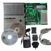
BOARD EVAL FOR MC9S08GB60
Manufacturer
Freescale Semiconductor
Type
MCUr
Datasheet
1.M68EVB908GB60E.pdf
(290 pages)
Specifications of M68EVB908GB60E
Contents
Module and Misc Hardware
Processor To Be Evaluated
MC9S08GB
Data Bus Width
8 bit
Interface Type
RS-232
Silicon Manufacturer
Freescale
Core Architecture
HCS08
Core Sub-architecture
HCS08
Silicon Core Number
MC9S08
Silicon Family Name
S08GB
Kit Contents
GB60 Evaluation Kit
Rohs Compliant
Yes
For Use With/related Products
MC9S08GB60
Lead Free Status / RoHS Status
Lead free / RoHS Compliant


In this particular case, the MCU has been attached to a PCB and the entire assembly is undergoing final
test with automated test equipment. A separate signal or message is provided to the MCU operating under
user provided software control. The MCU initiates a trim procedure as outlined in
tester supplies a precision reference signal.
If the intended bus frequency is near the maximum allowed for the device, it is recommended to trim using
a reduction divisor (R) twice the final value. Once the trim procedure is complete, the reduction divisor
can be restored. This will prevent accidental overshoot of the maximum clock frequency.
7.5
Refer to the direct-page register summary in the
assignments for all ICG registers. This section refers to registers and control bits only by their names. A
Freescale-provided equate or header file is used to translate these names into the appropriate absolute
addresses.
Freescale Semiconductor
Initial conditions:
1) Clock supplied from ATE has 500 µs duty period
2) ICG configured for internal reference with 4 MHz bus
ICG Registers and Control Bits
INCREASES THE FREQUENCY)
(DECREASING ICGTRM
ICGTRM - 128 / (2**n)
COUNT < EXPECTED = 500
(RUNNING TOO SLOW)
ICGTRM =
n = n + 1
IS n > 8?
(COUNT = # OF BUS CLOCKS / 4)
DECREASES THE FREQUENCY)
MC9S08GB/GT Data Sheet, Rev. 2.3
NO
START TRIM PROCEDURE
INCOMING CLOCK WIDTH
Figure 7-11. Trim Procedure
(INCREASING ICGTRM
ICGTRM = $80, n = 1
ICGTRM + 128 / (2**n)
CASE STATEMENT
ICGTRM =
MEASURE
YES
.
Memory
COUNT > EXPECTED = 500
(RUNNING TOO FAST)
chapter of this data sheet for the absolute address
COUNT = EXPECTED = 500
ICG Registers and Control Bits
Figure 7-11
STORE ICGTRM VALUE
IN NON-VOLATILE
CONTINUE
MEMORY
while the
117
Related parts for M68EVB908GB60E
Image
Part Number
Description
Manufacturer
Datasheet
Request
R

Part Number:
Description:
Manufacturer:
Freescale Semiconductor, Inc
Datasheet:
Part Number:
Description:
Manufacturer:
Freescale Semiconductor, Inc
Datasheet:
Part Number:
Description:
Manufacturer:
Freescale Semiconductor, Inc
Datasheet:
Part Number:
Description:
Manufacturer:
Freescale Semiconductor, Inc
Datasheet:
Part Number:
Description:
Manufacturer:
Freescale Semiconductor, Inc
Datasheet:
Part Number:
Description:
Manufacturer:
Freescale Semiconductor, Inc
Datasheet:
Part Number:
Description:
Manufacturer:
Freescale Semiconductor, Inc
Datasheet:
Part Number:
Description:
Manufacturer:
Freescale Semiconductor, Inc
Datasheet:
Part Number:
Description:
Manufacturer:
Freescale Semiconductor, Inc
Datasheet:
Part Number:
Description:
Manufacturer:
Freescale Semiconductor, Inc
Datasheet:
Part Number:
Description:
Manufacturer:
Freescale Semiconductor, Inc
Datasheet:
Part Number:
Description:
Manufacturer:
Freescale Semiconductor, Inc
Datasheet:
Part Number:
Description:
Manufacturer:
Freescale Semiconductor, Inc
Datasheet:
Part Number:
Description:
Manufacturer:
Freescale Semiconductor, Inc
Datasheet:
Part Number:
Description:
Manufacturer:
Freescale Semiconductor, Inc
Datasheet: