M68EVB908GB60E Freescale Semiconductor, M68EVB908GB60E Datasheet - Page 157
M68EVB908GB60E
Manufacturer Part Number
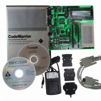
M68EVB908GB60E
Description
BOARD EVAL FOR MC9S08GB60
Manufacturer
Freescale Semiconductor
Type
MCUr
Datasheet
1.M68EVB908GB60E.pdf
(290 pages)
Specifications of M68EVB908GB60E
Contents
Module and Misc Hardware
Processor To Be Evaluated
MC9S08GB
Data Bus Width
8 bit
Interface Type
RS-232
Silicon Manufacturer
Freescale
Core Architecture
HCS08
Core Sub-architecture
HCS08
Silicon Core Number
MC9S08
Silicon Family Name
S08GB
Kit Contents
GB60 Evaluation Kit
Rohs Compliant
Yes
For Use With/related Products
MC9S08GB60
Lead Free Status / RoHS Status
Lead free / RoHS Compliant


register (TPMxCnVH:TPMxCnVL). The polarity of this PWM signal is determined by the setting in the
ELSnA control bit. Duty cycle cases of 0 percent and 100 percent are possible.
As
(duty cycle) of the PWM signal. The time between the modulus overflow and the output compare is the
pulse width. If ELSnA = 0, the counter overflow forces the PWM signal high and the output compare
forces the PWM signal low. If ELSnA = 1, the counter overflow forces the PWM signal low and the output
compare forces the PWM signal high.
When the channel value register is set to $0000, the duty cycle is 0 percent. By setting the timer channel
value register (TPMxCnVH:TPMxCnVL) to a value greater than the modulus setting, 100 percent duty
cycle can be achieved. This implies that the modulus setting must be less than $FFFF to get 100 percent
duty cycle.
Because the HCS08 is a family of 8-bit MCUs, the settings in the timer channel registers are buffered to
ensure coherent 16-bit updates and to avoid unexpected PWM pulse widths. Writes to either register,
TPMxCnVH or TPMxCnVL, write to buffer registers. In edge-PWM mode, values are transferred to the
corresponding timer channel registers only after both 8-bit bytes of a 16-bit register have been written and
the value in the TPMxCNTH:TPMxCNTL counter is $0000. (The new duty cycle does not take effect until
the next full period.)
10.5.3
This type of PWM output uses the up-/down-counting mode of the timer counter (CPWMS = 1). The
output compare value in TPMxCnVH:TPMxCnVL determines the pulse width (duty cycle) of the PWM
signal and the period is determined by the value in TPMxMODH:TPMxMODL.
TPMxMODH:TPMxMODL should be kept in the range of $0001 to $7FFF because values outside this
range can produce ambiguous results. ELSnA will determine the polarity of the CPWM output.
If the channel value register TPMxCnVH:TPMxCnVL is zero or negative (bit 15 set), the duty cycle will
be 0 percent. If TPMxCnVH:TPMxCnVL is a positive value (bit 15 clear) and is greater than the (nonzero)
modulus setting, the duty cycle will be 100 percent because the duty cycle compare will never occur. This
implies the usable range of periods set by the modulus register is $0001 through $7FFE ($7FFF if
Freescale Semiconductor
Figure 10-3
Center-Aligned PWM Mode
shows, the output compare value in the TPM channel registers determines the pulse width
TPMxC
OVERFLOW
Figure 10-3. PWM Period and Pulse Width (ELSnA = 0)
pulse width = 2 x (TPMxCnVH:TPMxCnVL)
PULSE
WIDTH
period = 2 x (TPMxMODH:TPMxMODL);
PERIOD
MC9S08GB/GT Data Sheet, Rev. 2.3
COMPARE
for TPMxMODH:TPMxMODL = $0001–$7FFF
OUTPUT
OVERFLOW
COMPARE
OUTPUT
OVERFLOW
COMPARE
OUTPUT
Functional Description
Eqn. 10-1
Eqn. 10-2
157
Related parts for M68EVB908GB60E
Image
Part Number
Description
Manufacturer
Datasheet
Request
R

Part Number:
Description:
Manufacturer:
Freescale Semiconductor, Inc
Datasheet:
Part Number:
Description:
Manufacturer:
Freescale Semiconductor, Inc
Datasheet:
Part Number:
Description:
Manufacturer:
Freescale Semiconductor, Inc
Datasheet:
Part Number:
Description:
Manufacturer:
Freescale Semiconductor, Inc
Datasheet:
Part Number:
Description:
Manufacturer:
Freescale Semiconductor, Inc
Datasheet:
Part Number:
Description:
Manufacturer:
Freescale Semiconductor, Inc
Datasheet:
Part Number:
Description:
Manufacturer:
Freescale Semiconductor, Inc
Datasheet:
Part Number:
Description:
Manufacturer:
Freescale Semiconductor, Inc
Datasheet:
Part Number:
Description:
Manufacturer:
Freescale Semiconductor, Inc
Datasheet:
Part Number:
Description:
Manufacturer:
Freescale Semiconductor, Inc
Datasheet:
Part Number:
Description:
Manufacturer:
Freescale Semiconductor, Inc
Datasheet:
Part Number:
Description:
Manufacturer:
Freescale Semiconductor, Inc
Datasheet:
Part Number:
Description:
Manufacturer:
Freescale Semiconductor, Inc
Datasheet:
Part Number:
Description:
Manufacturer:
Freescale Semiconductor, Inc
Datasheet:
Part Number:
Description:
Manufacturer:
Freescale Semiconductor, Inc
Datasheet: