M68EVB908GB60E Freescale Semiconductor, M68EVB908GB60E Datasheet - Page 221
M68EVB908GB60E
Manufacturer Part Number
M68EVB908GB60E
Description
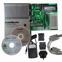
BOARD EVAL FOR MC9S08GB60
Manufacturer
Freescale Semiconductor
Type
MCUr
Datasheet
1.M68EVB908GB60E.pdf
(290 pages)
Specifications of M68EVB908GB60E
Contents
Module and Misc Hardware
Processor To Be Evaluated
MC9S08GB
Data Bus Width
8 bit
Interface Type
RS-232
Silicon Manufacturer
Freescale
Core Architecture
HCS08
Core Sub-architecture
HCS08
Silicon Core Number
MC9S08
Silicon Family Name
S08GB
Kit Contents
GB60 Evaluation Kit
Rohs Compliant
Yes
For Use With/related Products
MC9S08GB60
Lead Free Status / RoHS Status
Lead free / RoHS Compliant


14.1
The ATD module is an analog-to-digital converter with a successive approximation register (SAR)
architecture with sample and hold.
14.1.1
14.1.2
The ATD has two modes for low power
14.1.2.1 Stop Mode
When the MCU goes into stop mode, the MCU stops the clocks and the ATD analog circuitry is turned off,
placing the module into a low-power state. Once in stop mode, the ATD module aborts any single or
continuous conversion in progress. Upon exiting stop mode, no conversions occur and the registers have
their previous values. As long as the ATDPU bit is set prior to entering stop mode, the module is reactivated
coming out of stop.
14.1.2.2 Power Down Mode
Clearing the ATDPU bit in register ATD1C also places the ATD module in a low-power state. The ATD
conversion clock is disabled and the analog circuitry is turned off, placing the module in power-down
mode. (This mode does not remove power to the ATD module.) Once in power-down mode, the ATD
module aborts any conversion in progress. Upon setting the ATDPU bit, the module is reactivated. During
power-down mode, the ATD registers are still accessible.
Note that the reset state of the ATDPU bit is zero. Therefore, the module is reset into the power-down state.
14.1.3
Figure 14-2
Freescale Semiconductor
•
•
•
•
•
•
•
•
•
8-/10-bit resolution
14.0 µsec, 10-bit single conversion time at a conversion frequency of 2 MHz
Left-/right-justified result data
Left-justified signed data mode
Conversion complete flag or conversion complete interrupt generation
Analog input multiplexer for up to eight analog input channels
Single or continuous conversion mode
Stop mode
Power-down mode
Introduction
Features
Modes of Operation
Block Diagram
illustrates the functional structure of the ATD module.
MC9S08GB/GT Data Sheet, Rev. 2.3
Introduction
221
Related parts for M68EVB908GB60E
Image
Part Number
Description
Manufacturer
Datasheet
Request
R

Part Number:
Description:
Manufacturer:
Freescale Semiconductor, Inc
Datasheet:
Part Number:
Description:
Manufacturer:
Freescale Semiconductor, Inc
Datasheet:
Part Number:
Description:
Manufacturer:
Freescale Semiconductor, Inc
Datasheet:
Part Number:
Description:
Manufacturer:
Freescale Semiconductor, Inc
Datasheet:
Part Number:
Description:
Manufacturer:
Freescale Semiconductor, Inc
Datasheet:
Part Number:
Description:
Manufacturer:
Freescale Semiconductor, Inc
Datasheet:
Part Number:
Description:
Manufacturer:
Freescale Semiconductor, Inc
Datasheet:
Part Number:
Description:
Manufacturer:
Freescale Semiconductor, Inc
Datasheet:
Part Number:
Description:
Manufacturer:
Freescale Semiconductor, Inc
Datasheet:
Part Number:
Description:
Manufacturer:
Freescale Semiconductor, Inc
Datasheet:
Part Number:
Description:
Manufacturer:
Freescale Semiconductor, Inc
Datasheet:
Part Number:
Description:
Manufacturer:
Freescale Semiconductor, Inc
Datasheet:
Part Number:
Description:
Manufacturer:
Freescale Semiconductor, Inc
Datasheet:
Part Number:
Description:
Manufacturer:
Freescale Semiconductor, Inc
Datasheet:
Part Number:
Description:
Manufacturer:
Freescale Semiconductor, Inc
Datasheet: