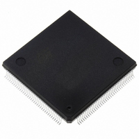
ST10F269Z2Q3 STMicroelectronics, ST10F269Z2Q3 Datasheet - Page 138

ST10F269Z2Q3
Manufacturer Part Number
ST10F269Z2Q3
Description
IC FLASH MEM 256KBIT 144-PQFP
Manufacturer
STMicroelectronics
Series
ST10r
Datasheet
1.ST10F269Z2Q3.pdf
(184 pages)
Specifications of ST10F269Z2Q3
Core Processor
ST10
Core Size
16-Bit
Speed
40MHz
Connectivity
CAN, EBI/EMI, SSC, UART/USART
Peripherals
POR, PWM, WDT
Number Of I /o
111
Program Memory Size
256KB (256K x 8)
Program Memory Type
FLASH
Ram Size
12K x 8
Voltage - Supply (vcc/vdd)
4.5 V ~ 5.5 V
Data Converters
A/D 16x10b
Oscillator Type
Internal
Operating Temperature
-40°C ~ 125°C
Package / Case
144-QFP
Processor Series
ST10F26x
Core
ST10
Data Bus Width
16 bit
Data Ram Size
12 KB
Interface Type
CAN, SSC, USART
Maximum Clock Frequency
40 MHz
Number Of Programmable I/os
111
Number Of Timers
2 x 16 bit
Operating Supply Voltage
0.3 V to 4 V
Maximum Operating Temperature
+ 125 C
Mounting Style
SMD/SMT
Minimum Operating Temperature
- 40 C
On-chip Adc
16 bit x 10 bit
Cpu Family
ST10
Device Core Size
16b
Frequency (max)
40MHz
Total Internal Ram Size
12KB
# I/os (max)
111
Number Of Timers - General Purpose
5
Operating Supply Voltage (typ)
5V
Operating Supply Voltage (max)
5.5V
Operating Supply Voltage (min)
4.5V
Instruction Set Architecture
CISC/RISC
Operating Temp Range
-40C to 125C
Operating Temperature Classification
Automotive
Mounting
Surface Mount
Pin Count
144
Package Type
PQFP
Lead Free Status / RoHS Status
Lead free / RoHS Compliant
Eeprom Size
-
Lead Free Status / Rohs Status
Lead free / RoHS Compliant
Other names
497-2042
Available stocks
Company
Part Number
Manufacturer
Quantity
Price
Company:
Part Number:
ST10F269Z2Q3
Manufacturer:
INFINEON
Quantity:
1 443
Company:
Part Number:
ST10F269Z2Q3
Manufacturer:
STMicroelectronics
Quantity:
10 000
Part Number:
ST10F269Z2Q3
Manufacturer:
ST
Quantity:
20 000
20 - SPECIAL FUNCTION REGISTER OVERVIEW
ST10F269
’1’: The on-chip Real Time Clock is enabled and can be accessed.
When both CAN are disabled via XPERCON
setting, then any access in the address range
00’EE00h - 00’EFFFh will be directed to external
memory interface, using the BUSCONx register
corresponding to address matching ADDRSELx
register. P4.4 and P4.7 can be used as General
Purpose I/O when CAN2 is not enabled, and P4.5
and P4.6 can be used as General Purpose I/O
when CAN1 is not enabled.
The default XPER selection after Reset is
identical to XBUS configuration of ST10C167:
XCAN1 is enabled, XCAN2 is disabled, XRAM1
(2K Byte compatible XRAM) is enabled, XRAM2
(new 8K Byte XRAM) is disabled.
Register XPERCON cannot be changed after the
global enabling of XPeripherals, i.e. after setting of
bit XPEN in SYSCON register.
In EMUlation mode, all the XPERipherals are
enabled (XPERCON bit are all set).
When the Real Time Clock is disabled (RTCEN =
0), the clock oscillator is switch off if ST10 enters
in power-down mode. Otherwise, when the Real
Time Clock is enabled, the bit RTCOFF of the
RTCCON
register
allows
to
choose
the
power-down mode of the clock oscillator.
138/184


