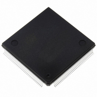
ST10F269Z2Q3 STMicroelectronics, ST10F269Z2Q3 Datasheet - Page 146

ST10F269Z2Q3
Manufacturer Part Number
ST10F269Z2Q3
Description
IC FLASH MEM 256KBIT 144-PQFP
Manufacturer
STMicroelectronics
Series
ST10r
Datasheet
1.ST10F269Z2Q3.pdf
(184 pages)
Specifications of ST10F269Z2Q3
Core Processor
ST10
Core Size
16-Bit
Speed
40MHz
Connectivity
CAN, EBI/EMI, SSC, UART/USART
Peripherals
POR, PWM, WDT
Number Of I /o
111
Program Memory Size
256KB (256K x 8)
Program Memory Type
FLASH
Ram Size
12K x 8
Voltage - Supply (vcc/vdd)
4.5 V ~ 5.5 V
Data Converters
A/D 16x10b
Oscillator Type
Internal
Operating Temperature
-40°C ~ 125°C
Package / Case
144-QFP
Processor Series
ST10F26x
Core
ST10
Data Bus Width
16 bit
Data Ram Size
12 KB
Interface Type
CAN, SSC, USART
Maximum Clock Frequency
40 MHz
Number Of Programmable I/os
111
Number Of Timers
2 x 16 bit
Operating Supply Voltage
0.3 V to 4 V
Maximum Operating Temperature
+ 125 C
Mounting Style
SMD/SMT
Minimum Operating Temperature
- 40 C
On-chip Adc
16 bit x 10 bit
Cpu Family
ST10
Device Core Size
16b
Frequency (max)
40MHz
Total Internal Ram Size
12KB
# I/os (max)
111
Number Of Timers - General Purpose
5
Operating Supply Voltage (typ)
5V
Operating Supply Voltage (max)
5.5V
Operating Supply Voltage (min)
4.5V
Instruction Set Architecture
CISC/RISC
Operating Temp Range
-40C to 125C
Operating Temperature Classification
Automotive
Mounting
Surface Mount
Pin Count
144
Package Type
PQFP
Lead Free Status / RoHS Status
Lead free / RoHS Compliant
Eeprom Size
-
Lead Free Status / Rohs Status
Lead free / RoHS Compliant
Other names
497-2042
Available stocks
Company
Part Number
Manufacturer
Quantity
Price
Company:
Part Number:
ST10F269Z2Q3
Manufacturer:
INFINEON
Quantity:
1 443
Company:
Part Number:
ST10F269Z2Q3
Manufacturer:
STMicroelectronics
Quantity:
10 000
Part Number:
ST10F269Z2Q3
Manufacturer:
ST
Quantity:
20 000
Table 43 : ADC Sampling and Conversion Timing (TQFP144 devices)
A complete conversion will take 14
time includes the conversion itself, the sample time and the time required to transfer the digital value to
the result register.
21.4 - AC characteristics
21.4.1 - Test Waveforms
Figure 66 : Input / Output Waveforms
Figure 67 : Float Waveforms
21.4.2 - Definition of Internal Timing
The internal operation of the ST10F269 is
controlled by the internal CPU clock f
edges of the CPU clock can trigger internal (for
146/184
ADCON.15/14
ADCTC
For timing purposes a port pin is no longer floating when V
It begins to float when a 100mV change from the loaded V
AC inputs during testing are driven at 2.4V for a logic ‘1’ and 0.4V for a logic ‘0’.
Timing measurements are made at V
00
01
10
11
0.45V
2.4V
V
Load
V
V
Reserved, do not use
Load
Load
TCL = 1/2 x f
+0.1V
-0.1V
TCL x 24
TCL x 96
TCL x 48
Conversion Clock t
XTAL
t
0.2V
0.2V
CC
At f
+ 2 t
DD
DD
CPU
CPU
Reserved
IH
+0.9
-0.1
0.375 s
0.75 s
CC
1.5 s
. Both
SC
Test Points
min for a logic ‘1’ and V
= 32MHz
+ 4 TCL (fastest convertion rate = 6.06 s at 32MHz). This
Reference
Timing
Points
V
V
OL
OH
0.2V
0.2V
example pipeline) or external (for example bus
cycles) operations.
The specification of the external timing (AC
Characteristics) therefore depends on the time
ADCON.13/12
DD
DD
ADSTC
-0.1
+0.9
00
01
10
11
OH
LOAD
/V
OL
IL
changes of ±100mV.
max for a logic ‘0’.
level occurs (I
t
t
t
CC
CC
CC
t
SC
t
CC
x 2
x 4
x 8
Sample Clock t
=
V
V
OL
OH
OH
+0.1V
-0.1V
/I
and ADCTC = 00
OL
At f
= 20mA).
CPU
0.375 s
ST10F269
0.75 s
1.50 s
3.00 s
SC
= 32MHz


