MC9S12C32CFAE25 Freescale Semiconductor, MC9S12C32CFAE25 Datasheet - Page 248
MC9S12C32CFAE25
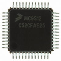
Manufacturer Part Number
MC9S12C32CFAE25
Description
IC MCU 32K FLASH 25MHZ 48-LQFP
Manufacturer
Freescale Semiconductor
Series
HCS12r
Datasheets
1.MC9S12GC16MFUE.pdf
(690 pages)
2.MC9S12C96CFUER.pdf
(26 pages)
3.MC9S12C32CFAE25.pdf
(2 pages)
4.MC9S12C32CPBE25.pdf
(36 pages)
Specifications of MC9S12C32CFAE25
Core Processor
HCS12
Core Size
16-Bit
Speed
25MHz
Connectivity
CAN, EBI/EMI, SCI, SPI
Peripherals
POR, PWM, WDT
Number Of I /o
31
Program Memory Size
32KB (32K x 8)
Program Memory Type
FLASH
Ram Size
2K x 8
Voltage - Supply (vcc/vdd)
2.35 V ~ 5.5 V
Data Converters
A/D 8x10b
Oscillator Type
Internal
Operating Temperature
-40°C ~ 85°C
Package / Case
48-LQFP
Processor Series
S12C
Core
HCS12
Data Bus Width
16 bit
Data Ram Size
2 KB
Interface Type
CAN/SCI/SPI
Maximum Clock Frequency
25 MHz
Number Of Programmable I/os
31
Number Of Timers
8
Maximum Operating Temperature
+ 85 C
Mounting Style
SMD/SMT
3rd Party Development Tools
EWHCS12
Development Tools By Supplier
M68EVB912C32EE
Minimum Operating Temperature
- 40 C
On-chip Adc
8-ch x 10-bit
For Use With
CML12C32SLK - KIT STUDENT LEARNING 16BIT HCS12
Lead Free Status / RoHS Status
Lead free / RoHS Compliant
Eeprom Size
-
Lead Free Status / Rohs Status
Lead free / RoHS Compliant
Available stocks
Company
Part Number
Manufacturer
Quantity
Price
Company:

Part Number:
MC9S12C32CFAE25
Manufacturer:
FREESCAL
Quantity:
240
Company:
Part Number:
MC9S12C32CFAE25
Manufacturer:
Freescale Semiconductor
Quantity:
10 000


Chapter 8 Analog-to-Digital Converter (ATD10B8C) Block Description
8.5.1.3
Configure how many conversions you want to perform in one sequence and define other settings in
ATDCTL3.
Example: Write S4C=1 to do 4 conversions per sequence.
8.5.1.4
Configure resolution, sampling time and ATD clock speed in ATDCTL4.
Example: Use default for resolution and sampling time by leaving SRES8, SMP1 and SMP0 clear. For a
bus clock of 40MHz write 9 to PR4-0, this gives an ATD clock of 0.5*40MHz/(9+1) = 2MHz which is
within the allowed range for f
8.5.1.5
Configure starting channel, single/multiple channel, continuous or single sequence and result data format
in ATDCTL5. Writing ATDCTL5 will start the conversion, so make sure your write ATDCTL5 in the last
step.
Example: Leave CC,CB,CA clear to start on channel AN0. Write MULT=1 to convert channel AN0 to
AN3 in a sequence (4 conversion per sequence selected in ATDCTL3).
8.5.2
8.5.2.1
Disable the ATD Interrupt by writing ASCIE=0 in ATDCTL2. This will also abort any ongoing conversion
sequence.
It is important to clear the interrupt enable at this point, prior to step 3, as depending on the device clock
gating it may not always be possible to clear it or the SCF flag once the module is disabled (ADPU=0).
8.5.2.2
Clear the SCF flag by writing a 1 in ATDSTAT0.
(Remaining flags will be cleared with the next start of a conversions, but SCF flag should be cleared to
avoid SCF interrupt.)
8.5.2.3
Power down ATD by writing ADPU=0 in ATDCTL2.
8.6
At reset the ATD10B8C is in a power down state. The reset state of each individual bit is listed within
Section 8.3.2, “Register Descriptions”
248
Resets
Aborting an A/D conversion
Step 3
Step 4
Step 5
Step 1
Step 2
Step 3
ATDCLK
MC9S12C-Family / MC9S12GC-Family
.
which details the registers and their bit-field.
Rev 01.24
Freescale Semiconductor
Related parts for MC9S12C32CFAE25
Image
Part Number
Description
Manufacturer
Datasheet
Request
R

Part Number:
Description:
Manufacturer:
Freescale Semiconductor, Inc
Datasheet:
Part Number:
Description:
Manufacturer:
Freescale Semiconductor, Inc
Datasheet:
Part Number:
Description:
Manufacturer:
Freescale Semiconductor, Inc
Datasheet:
Part Number:
Description:
Manufacturer:
Freescale Semiconductor, Inc
Datasheet:
Part Number:
Description:
Manufacturer:
Freescale Semiconductor, Inc
Datasheet:
Part Number:
Description:
Manufacturer:
Freescale Semiconductor, Inc
Datasheet:
Part Number:
Description:
Manufacturer:
Freescale Semiconductor, Inc
Datasheet:
Part Number:
Description:
Manufacturer:
Freescale Semiconductor, Inc
Datasheet:
Part Number:
Description:
Manufacturer:
Freescale Semiconductor, Inc
Datasheet:
Part Number:
Description:
Manufacturer:
Freescale Semiconductor, Inc
Datasheet:
Part Number:
Description:
Manufacturer:
Freescale Semiconductor, Inc
Datasheet:
Part Number:
Description:
Manufacturer:
Freescale Semiconductor, Inc
Datasheet:
Part Number:
Description:
Manufacturer:
Freescale Semiconductor, Inc
Datasheet:
Part Number:
Description:
Manufacturer:
Freescale Semiconductor, Inc
Datasheet:
Part Number:
Description:
Manufacturer:
Freescale Semiconductor, Inc
Datasheet: