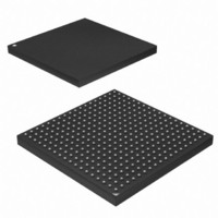
AT91SAM9M10-CU Atmel, AT91SAM9M10-CU Datasheet - Page 721

AT91SAM9M10-CU
Manufacturer Part Number
AT91SAM9M10-CU
Description
IC MCU 16/32BIT ARM9 324TFBGA
Manufacturer
Atmel
Series
AT91SAMr
Specifications of AT91SAM9M10-CU
Core Processor
ARM9
Core Size
16/32-Bit
Speed
400MHz
Connectivity
EBI/EMI, Ethernet, I²C, SPI, SSC, UART/USART, USB
Peripherals
AC'97, DMA, LCD, POR, PWM, WDT
Number Of I /o
160
Program Memory Size
64KB (64K x 8)
Program Memory Type
ROM
Ram Size
128K x 8
Voltage - Supply (vcc/vdd)
0.9 V ~ 1.1 V
Data Converters
A/D 8x10b
Oscillator Type
Internal
Operating Temperature
-40°C ~ 85°C
Package / Case
324-TFBGA
Processor Series
AT91SAMx
Core
ARM926EJ-S
Data Bus Width
32 bit
Data Ram Size
32 KB
Interface Type
2-Wire, SPI, USART
Maximum Clock Frequency
133 MHz
Number Of Programmable I/os
5
Number Of Timers
2 x 16 bit
Operating Supply Voltage
1.65 V to 3.6 V
Maximum Operating Temperature
+ 85 C
Mounting Style
SMD/SMT
3rd Party Development Tools
JTRACE-ARM-2M, MDK-ARM, RL-ARM, ULINK2
Development Tools By Supplier
AT91SAM-ICE, AT91-ISP, AT91SAM9M10-G45-EK
Controller Family/series
AT91
No. Of I/o's
160
Ram Memory Size
64KB
Cpu Speed
400MHz
No. Of Timers
2
Rohs Compliant
Yes
Cpu Family
AT91
Device Core
ARM926EJ-S
Device Core Size
32b
Frequency (max)
400MHz
Total Internal Ram Size
64KB
# I/os (max)
160
Number Of Timers - General Purpose
7
Operating Supply Voltage (typ)
1.8/2.5/3.3V
Operating Supply Voltage (max)
1.1/1.95/3.6V
Operating Supply Voltage (min)
0.9/1.65/1.8/3V
On-chip Adc
8-chx10-bit
Instruction Set Architecture
RISC
Operating Temp Range
-40C to 85C
Operating Temperature Classification
Industrial
Mounting
Surface Mount
Pin Count
324
Package Type
TFBGA
Lead Free Status / RoHS Status
Lead free / RoHS Compliant
Eeprom Size
-
Lead Free Status / Rohs Status
Lead free / RoHS Compliant
Available stocks
Company
Part Number
Manufacturer
Quantity
Price
Company:
Part Number:
AT91SAM9M10-CU
Manufacturer:
Atmel
Quantity:
996
- Current page: 721 of 1404
- Download datasheet (22Mb)
35.8.6.3
6355B–ATARM–21-Jun-10
Block Length is Not Multiple of 4, with Padding Value (ROPT field in HSMCI_DMA register set to 1)
When the ROPT field is set to one, The DMA Controller performs only WORD access on the bus
to transfer a non-multiple of 4 block length. Unlike previous flow, in which the transfer size is
rounded to the nearest multiple of 4.
3. Wait for XFRDONE in HSMCI_SR register.
1. Program the HSMCI Interface, see previous flow.
2. Program the DMA Controller
j.
k. The LLI_B.DMAC_SADDRx field in memory must be set with the starting address
l.
m. Program LLI_B.DMAC_CTRLAx with the following field’s values:
n. Program LLI_B.DMAC_CTRLBx with the following field’s values:
o. Program LLI_B.DMAC_CFGx memory location for channel x with the following
– FIFOCFG defines the watermark of the DMA channel FIFO.
– SRC_H2SEL is set to true to enable hardware handshaking on the destination.
– SRC_PER is programmed with the hardware handshaking ID of the targeted HSMCI
p. Program LLI_B.DMAC_DSCR with 0.
q. Program DMAC_CTRLBx register for channel x with 0. its content is updated with
r.
s. Enable Channel x writing one to DMAC_CHER[x]. The DMAC is ready and waiting
– ROPT field is set to 1.
Host Controller.
descriptor on the second byte oriented descriptor. When block_length[1:0] is equal
to 0 (multiple of 4) LLI_W.DMAC_DSCRx points to 0, only LLI_W is relevant.
Program the channel registers in the Memory for the second descriptor. This
descriptor will be byte oriented. This descriptor is referred to as LLI_B, standing for
LLI Byte oriented.
of the HSMCI_FIFO address.
The LLI_B.DMAC_DADDRx is not relevant if previous word aligned descriptor was
enabled. If 1, 2 or 3 bytes are transferred that address is user defined and not word
aligned.
–DST_WIDTH is set to BYTE.
–SRC_WIDTH is set to BYTE.
–SCSIZE must be set according to the value of HSMCI_DMA, CHKSIZE field.
–BTSIZE is programmed with block_length[1:0]. (last 1, 2, or 3 bytes of the buffer).
–DST_INCR is set to INCR
–SRC_INCR is set to INCR
–FC field is programmed with peripheral to memory flow control mode.
–Both SRC_DSCR and DST_DSCR are set to 1 (descriptor fetch is disabled) or
–DIF and SIF are set with their respective layer ID. If SIF is different from DIF, DMA
field’s values:
the LLI fetch operation.
Program DMAC_DSCRx with the address of LLI_W if block_length greater than 4
else with address of LLI_B.
for request.
Next descriptor location points to 0.
Controller is able to prefetch data and write HSMCI simultaneously.
AT91SAM9M10
721
Related parts for AT91SAM9M10-CU
Image
Part Number
Description
Manufacturer
Datasheet
Request
R

Part Number:
Description:
MCU, MPU & DSP Development Tools KICKSTART KIT FOR AT91SAM9 PLUS
Manufacturer:
IAR Systems

Part Number:
Description:
DEV KIT FOR AVR/AVR32
Manufacturer:
Atmel
Datasheet:

Part Number:
Description:
INTERVAL AND WIPE/WASH WIPER CONTROL IC WITH DELAY
Manufacturer:
ATMEL Corporation
Datasheet:

Part Number:
Description:
Low-Voltage Voice-Switched IC for Hands-Free Operation
Manufacturer:
ATMEL Corporation
Datasheet:

Part Number:
Description:
MONOLITHIC INTEGRATED FEATUREPHONE CIRCUIT
Manufacturer:
ATMEL Corporation
Datasheet:

Part Number:
Description:
AM-FM Receiver IC U4255BM-M
Manufacturer:
ATMEL Corporation
Datasheet:

Part Number:
Description:
Monolithic Integrated Feature Phone Circuit
Manufacturer:
ATMEL Corporation
Datasheet:

Part Number:
Description:
Multistandard Video-IF and Quasi Parallel Sound Processing
Manufacturer:
ATMEL Corporation
Datasheet:

Part Number:
Description:
High-performance EE PLD
Manufacturer:
ATMEL Corporation
Datasheet:

Part Number:
Description:
8-bit Flash Microcontroller
Manufacturer:
ATMEL Corporation
Datasheet:

Part Number:
Description:
2-Wire Serial EEPROM
Manufacturer:
ATMEL Corporation
Datasheet:


