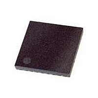
ATTINY861-15MZ Atmel, ATTINY861-15MZ Datasheet - Page 122

ATTINY861-15MZ
Manufacturer Part Number
ATTINY861-15MZ
Description
MCU AVR 8K FLASH 15MHZ 32-QFN
Manufacturer
Atmel
Series
AVR® ATtinyr
Datasheet
1.ATTINY861-15MZ.pdf
(236 pages)
Specifications of ATTINY861-15MZ
Package / Case
32-VQFN Exposed Pad, 32-HVQFN, 32-SQFN, 32-DHVQFN
Voltage - Supply (vcc/vdd)
2.7 V ~ 5.5 V
Operating Temperature
-40°C ~ 125°C
Speed
16MHz
Number Of I /o
16
Eeprom Size
512 x 8
Core Processor
AVR
Program Memory Type
FLASH
Ram Size
512 x 8
Program Memory Size
8KB (8K x 8)
Data Converters
A/D 11x10b
Oscillator Type
Internal
Peripherals
Brown-out Detect/Reset, POR, PWM, WDT
Connectivity
USI
Core Size
8-Bit
Processor Series
ATTINY8x
Core
AVR8
Data Bus Width
8 bit
Data Ram Size
512 B
Interface Type
SPI
Maximum Clock Frequency
16 MHz
Number Of Programmable I/os
16
Number Of Timers
2
Maximum Operating Temperature
+ 85 C
Mounting Style
SMD/SMT
3rd Party Development Tools
EWAVR, EWAVR-BL
Development Tools By Supplier
ATAVRDRAGON, ATSTK500, ATSTK600, ATAVRISP2, ATAVRONEKIT, ATAVRMC320
Minimum Operating Temperature
- 40 C
On-chip Adc
10 bit, 11 Channel
Lead Free Status / RoHS Status
Lead free / RoHS Compliant
Available stocks
Company
Part Number
Manufacturer
Quantity
Price
Company:
Part Number:
ATTINY861-15MZ
Manufacturer:
ATMEL
Quantity:
1 465
- Current page: 122 of 236
- Download datasheet (2Mb)
16.11.9
16.11.10 OCR1C – Timer/Counter1 Output Compare Register C
122
ATtiny261/461/861
OCR1B – Timer/Counter1 Output Compare Register B
The Timer/Counter Output Compare Register A contains data to be continuously compared with
Timer/Counter1. Actions on compare matches are specified in TCCR1A. A compare match does
only occur if Timer/Counter1 counts to the OCR1A value. A software write that sets TCNT1 and
OCR1A to the same value does not generate a compare match.
A compare match will set the compare interrupt flag OCF1A after a synchronization delay follow-
ing the compare event.
Note that, if 10-bit accuracy is used special procedures must be followed when accessing the
internal 10-bit Ouput Compare Registers via the 8-bit AVR data bus. These procedures are
described in section
The output compare register B is an 8-bit read/write register.
The Timer/Counter Output Compare Register B contains data to be continuously compared with
Timer/Counter1. Actions on compare matches are specified in TCCR1. A compare match does
only occur if Timer/Counter1 counts to the OCR1B value. A software write that sets TCNT1 and
OCR1B to the same value does not generate a compare match.
A compare match will set the compare interrupt flag OCF1B after a synchronization delay follow-
ing the compare event.
Note that, if 10-bit accuracy is used special procedures must be followed when accessing the
internal 10-bit Output Compare Registers via the 8-bit AVR data bus. These procedures are
described in section
The output compare register C is an 8-bit read/write register.
The Timer/Counter Output Compare Register C contains data to be continuously compared with
Timer/Counter1, and a compare match will clear TCNT1. This register has the same function in
Normal mode and PWM modes.
Note that, if a smaller value than three is written to the Output Compare Register C, the value is
automatically replaced by three as it is a minumum value allowed to be written to this register.
Note that, if 10-bit accuracy is used special procedures must be followed when accessing the
internal 10-bit Output Compare Registers via the 8-bit AVR data bus. These procedures are
described in section
Bit
0x2C (0x4C)
Read/Write
Initial value
Bit
0x2B (0x4B)
Read/Write
Initial value
MSB
MSB
R/W
R/W
7
0
7
1
”Accessing 10-Bit Registers” on page
”Accessing 10-Bit Registers” on page
”Accessing 10-Bit Registers” on page
R/W
R/W
6
0
6
1
R/W
R/W
5
0
5
1
R/W
R/W
4
0
4
1
R/W
R/W
3
0
3
1
110.
110.
110.
R/W
R/W
2
0
2
1
R/W
R/W
1
0
1
1
LSB
R/W
LSB
R/W
0
0
0
1
2588B–AVR–11/06
OCR1B
OCR1C
Related parts for ATTINY861-15MZ
Image
Part Number
Description
Manufacturer
Datasheet
Request
R

Part Number:
Description:
Manufacturer:
Atmel Corporation
Datasheet:

Part Number:
Description:
Manufacturer:
Atmel Corporation
Datasheet:

Part Number:
Description:
IC MCU AVR 8K FLASH 20MHZ 32-QFN
Manufacturer:
Atmel
Datasheet:

Part Number:
Description:
IC MCU AVR 8K FLASH 20MHZ 20SOIC
Manufacturer:
Atmel
Datasheet:

Part Number:
Description:
MCU AVR 8K FLASH 15MHZ 20-SOIC
Manufacturer:
Atmel
Datasheet:

Part Number:
Description:
MCU AVR 8KB FLASH 15MHZ 32-VQFN
Manufacturer:
Atmel
Datasheet:

Part Number:
Description:
Microcontrollers (MCU) 8kB Flash 0.512kB EEPROM 16 I/O Pins
Manufacturer:
Atmel
Datasheet:

Part Number:
Description:
8-bit Microcontrollers - MCU 8KB FL 512B EE 512B SRAM 20MHZ IND 5V
Manufacturer:
Atmel

Part Number:
Description:
IC, MCU, 8BIT, 2K FLASH, 20SOIC
Manufacturer:
Atmel
Datasheet:

Part Number:
Description:
IC, MCU, 8BIT, 2K FLASH, 20PDIP
Manufacturer:
Atmel
Datasheet:


