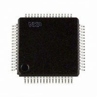
P89LPC9402FBD,557 NXP Semiconductors, P89LPC9402FBD,557 Datasheet - Page 38

P89LPC9402FBD,557
Manufacturer Part Number
P89LPC9402FBD,557
Description
IC 80C51 MCU FLASH 8K 64-LQFP
Manufacturer
NXP Semiconductors
Series
LPC900r
Datasheet
1.P89LPC9402FBD557.pdf
(60 pages)
Specifications of P89LPC9402FBD,557
Program Memory Type
FLASH
Program Memory Size
8KB (8K x 8)
Package / Case
64-LQFP
Core Processor
8051
Core Size
8-Bit
Speed
18MHz
Connectivity
I²C, SPI, UART/USART
Peripherals
Brown-out Detect/Reset, LCD, LED, POR, PWM, WDT
Number Of I /o
23
Ram Size
256 x 8
Voltage - Supply (vcc/vdd)
2.4 V ~ 3.6 V
Oscillator Type
Internal
Operating Temperature
-40°C ~ 85°C
Processor Series
P89LPC
Core
80C51
Data Bus Width
8 bit
Data Ram Size
256 B
Interface Type
I2C, SPI, UART
Maximum Clock Frequency
18 MHz
Number Of Programmable I/os
20
Number Of Timers
2
Operating Supply Voltage
2.4 V to 3.6 V
Maximum Operating Temperature
+ 85 C
Mounting Style
SMD/SMT
3rd Party Development Tools
PK51, CA51, A51, ULINK2
Minimum Operating Temperature
- 40 C
Lead Free Status / RoHS Status
Lead free / RoHS Compliant
Eeprom Size
-
Data Converters
-
Lead Free Status / Rohs Status
Lead free / RoHS Compliant
Other names
935288631557
Available stocks
Company
Part Number
Manufacturer
Quantity
Price
Company:
Part Number:
P89LPC9402FBD,557
Manufacturer:
NXP Semiconductors
Quantity:
10 000
NXP Semiconductors
Table 8.
P89LPC9402_1
Product data sheet
Number of
Backplanes
4
3
2
1
Selection of display configurations
7.27.4.1 Internal clock
7.27.1 General description
7.27.2 Functional description
7.27.3 LCD bias voltages
7.27.4 Oscillator
7.27 LCD driver
Segments
128
96
64
32
The LCD segment driver in the P89LPC9402 can interface to most LCDs using low
multiplex rates. It generates the drive signals for static or multiplexed LCDs containing up
to four backplanes and up to 32 segments. The LCD controller communicates to a host
using the I
LCD driver are available on the P89LPC9402 providing system flexibility. Communication
overhead to manage the display is minimized by an on-chip display RAM with
auto-increment addressing, hardware subaddressing, and display memory switching
(static and duplex drive modes).
The LCD controller is a versatile peripheral device designed to interface microcontrollers
to a wide variety of LCDs. It can directly drive any static or multiplexed LCD containing up
to four backplanes and up to 32 segments. The display configurations possible with the
LCD controller depend on the number of active backplane outputs required. A selection of
display configurations is shown in
in a typical system.
The microcontroller communicates to the LCD controller using the I
appropriate biasing voltages for the multiplexed LCD waveforms are generated internally.
The only other connections required to complete the system are to the power supplies
(V
LCD biasing voltages are obtained from an internal voltage divider consisting of three
series resistors connected between V
compensated externally via the supply to pin V
multiplexing of the LCD based on programmable configurations.
An internal oscillator provides the clock signals for the internal logic of the LCD controller
and its LCD drive signals. After power-up, pin SDA must be HIGH to guarantee that the
clock starts.
DD
, V
SS
7-segments numeric
Digits
16
12
8
4
2
and V
C-bus. The I
LCD
) and the LCD panel chosen for the application.
Rev. 01 — 22 April 2009
2
C-bus clock and data signals for both the microcontroller and the
8-bit microcontroller with accelerated two-clock 80C51 core
Indicator
symbols
16
12
8
4
Table
LCD
8. All of these configurations can be implemented
and V
14- segments alphanumeric
Characters
8
6
4
2
LCD
SS
. The LCD voltage can be temperature
. A voltage selector drives the
Indicator
symbols
16
12
8
4
P89LPC9402
2
C-bus.The
© NXP B.V. 2009. All rights reserved.
Dot matrix
128
96
64
32
38 of 60


