MC68HC908GP32CP Freescale Semiconductor, MC68HC908GP32CP Datasheet - Page 192
MC68HC908GP32CP
Manufacturer Part Number
MC68HC908GP32CP
Description
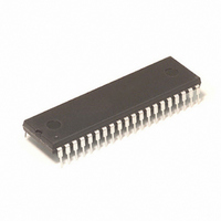
IC MCU 8MHZ 32K FLASH 40-DIP
Manufacturer
Freescale Semiconductor
Series
HC08r
Datasheet
1.MC68HC908GP32CFB.pdf
(410 pages)
Specifications of MC68HC908GP32CP
Core Processor
HC08
Core Size
8-Bit
Speed
8MHz
Connectivity
SCI, SPI
Peripherals
LVD, POR, PWM
Number Of I /o
33
Program Memory Size
32KB (32K x 8)
Program Memory Type
FLASH
Ram Size
512 x 8
Voltage - Supply (vcc/vdd)
2.7 V ~ 5.5 V
Data Converters
A/D 8x8b
Oscillator Type
Internal
Operating Temperature
-40°C ~ 85°C
Package / Case
40-DIP (0.600", 15.24mm)
For Use With
M68EVB908GP32 - BOARD EVALUATION FOR HC908GP32
Lead Free Status / RoHS Status
Contains lead / RoHS non-compliant
Eeprom Size
-
Available stocks
Company
Part Number
Manufacturer
Quantity
Price
Company:

Part Number:
MC68HC908GP32CP
Manufacturer:
ROCKWELL
Quantity:
201
Part Number:
MC68HC908GP32CP
Manufacturer:
MOTOROLA/摩托罗拉
Quantity:
20 000


Low-Voltage Inhibit (LVI)
14.4 Functional Description
Technical Data
190
NOTE:
NOTE:
Figure 14-1
out of reset. The LVI module contains a bandgap reference circuit and
comparator. Clearing the LVI power disable bit, LVIPWRD, enables the
LVI to monitor V
enables the LVI module to generate a reset when V
voltage, V
enables the LVI to operate in stop mode. Setting the LVI 5-V or 3-V trip
point bit, LVI5OR3, enables the trip point voltage, V
configured for 5-V operation. Clearing the LVI5OR3 bit enables the trip
point voltage, V
points are shown in
After a power-on reset (POR) the LVI’s default mode of operation is 3 V.
If a 5-V system is used, the user must set the LVI5OR3 bit to raise the
trip point to 5-V operation. Note that this must be done after every power-
on reset since the default will revert back to 3-V mode after each power-
on reset. If the V
the 3-V mode trip voltage when POR is released, the part will operate
because V
care must be taken to ensure that V
after POR is released.
If the user requires 5-V mode and sets the LVI5OR3 bit after a power-on
reset while the V
MCU will immediately go into reset. The LVI in this case will hold the part
in reset until either V
which will release reset or V
re-trigger the power-on reset and reset the trip point to 3-V operation.
LVISTOP, LVIPWRD, LVI5OR3, and LVIRSTD are in the configuration
register (CONFIG1).
LVI’s configuration bits. Once an LVI reset occurs, the MCU remains in
reset until V
exit reset.
the interaction between the SIM and the LVI. The output of the
comparator controls the state of the LVIOUT flag in the LVI status
register (LVISR).
TRIPF
See 19.4.2.5 Low-Voltage Inhibit (LVI) Reset
TRIPF
DD
shows the structure of the LVI module. The LVI is enabled
Low-Voltage Inhibit (LVI)
rises above a voltage, V
. Setting the LVI enable in stop mode bit, LVISTOP,
TRIPF
DD
DD
defaults to 3-V mode after a POR. So, in a 5-V system
DD
voltage. Clearing the LVI reset disable bit, LVIRSTD,
supply is below the 5-V mode trip voltage but above
supply is not above the V
Section 23. Electrical
, to be configured for 3-V operation. The actual trip
DD
See 8.3 Functional Description
goes above the rising 5-V trip point, V
DD
decreases to approximately 0 V which will
MC68HC908GP32
DD
is above the 5-V mode trip voltage
TRIPR
Specifications.
, which causes the MCU to
TRIPR
•
MC68HC08GP32
for 5-V mode, the
TRIPF
DD
for details of the
falls below a
, to be
for details of
MOTOROLA
TRIPR
—
Rev. 6
,
Related parts for MC68HC908GP32CP
Image
Part Number
Description
Manufacturer
Datasheet
Request
R

Part Number:
Description:
Manufacturer:
Freescale Semiconductor, Inc
Datasheet:
Part Number:
Description:
Manufacturer:
Freescale Semiconductor, Inc
Datasheet:
Part Number:
Description:
Manufacturer:
Freescale Semiconductor, Inc
Datasheet:
Part Number:
Description:
Manufacturer:
Freescale Semiconductor, Inc
Datasheet:
Part Number:
Description:
Manufacturer:
Freescale Semiconductor, Inc
Datasheet:
Part Number:
Description:
Manufacturer:
Freescale Semiconductor, Inc
Datasheet:
Part Number:
Description:
Manufacturer:
Freescale Semiconductor, Inc
Datasheet:
Part Number:
Description:
Manufacturer:
Freescale Semiconductor, Inc
Datasheet:
Part Number:
Description:
Manufacturer:
Freescale Semiconductor, Inc
Datasheet:
Part Number:
Description:
Manufacturer:
Freescale Semiconductor, Inc
Datasheet:
Part Number:
Description:
Manufacturer:
Freescale Semiconductor, Inc
Datasheet:
Part Number:
Description:
Manufacturer:
Freescale Semiconductor, Inc
Datasheet:
Part Number:
Description:
Manufacturer:
Freescale Semiconductor, Inc
Datasheet:
Part Number:
Description:
Manufacturer:
Freescale Semiconductor, Inc
Datasheet:
Part Number:
Description:
Manufacturer:
Freescale Semiconductor, Inc
Datasheet: