MC68HC908GP32CP Freescale Semiconductor, MC68HC908GP32CP Datasheet - Page 263
MC68HC908GP32CP
Manufacturer Part Number
MC68HC908GP32CP
Description
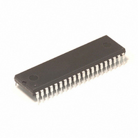
IC MCU 8MHZ 32K FLASH 40-DIP
Manufacturer
Freescale Semiconductor
Series
HC08r
Datasheet
1.MC68HC908GP32CFB.pdf
(410 pages)
Specifications of MC68HC908GP32CP
Core Processor
HC08
Core Size
8-Bit
Speed
8MHz
Connectivity
SCI, SPI
Peripherals
LVD, POR, PWM
Number Of I /o
33
Program Memory Size
32KB (32K x 8)
Program Memory Type
FLASH
Ram Size
512 x 8
Voltage - Supply (vcc/vdd)
2.7 V ~ 5.5 V
Data Converters
A/D 8x8b
Oscillator Type
Internal
Operating Temperature
-40°C ~ 85°C
Package / Case
40-DIP (0.600", 15.24mm)
For Use With
M68EVB908GP32 - BOARD EVALUATION FOR HC908GP32
Lead Free Status / RoHS Status
Contains lead / RoHS non-compliant
Eeprom Size
-
Available stocks
Company
Part Number
Manufacturer
Quantity
Price
Company:

Part Number:
MC68HC908GP32CP
Manufacturer:
ROCKWELL
Quantity:
201
Part Number:
MC68HC908GP32CP
Manufacturer:
MOTOROLA/摩托罗拉
Quantity:
20 000


MC68HC908GP32
MOTOROLA
•
MC68HC08GP32
M — Mode (Character Length) Bit
WAKE — Wakeup Condition Bit
ILTY — Idle Line Type Bit
PEN — Parity Enable Bit
This read/write bit determines whether SCI characters are eight or
nine bits long.
stop bit, as a receiver wakeup signal, or as a parity bit. Reset clears
the M bit.
This read/write bit determines which condition wakes up the SCI: a
logic 1 (address mark) in the most significant bit position of a received
character or an idle condition on the PTE1/RxD pin. Reset clears the
WAKE bit.
This read/write bit determines when the SCI starts counting logic 1s
as idle character bits. The counting begins either after the start bit or
after the stop bit. If the count begins after the start bit, then a string of
logic 1s preceding the stop bit may cause false recognition of an idle
character. Beginning the count after the stop bit avoids false idle
character recognition, but requires properly synchronized
transmissions. Reset clears the ILTY bit.
This read/write bit enables the SCI parity function.
When enabled, the parity function inserts a parity bit in the most
significant bit position.
Serial Communications Interface Module (SCI)
1 = 9-bit SCI characters
0 = 8-bit SCI characters
1 = Address mark wakeup
0 = Idle line wakeup
1 = Idle character bit count begins after stop bit
0 = Idle character bit count begins after start bit
1 = Parity function enabled
0 = Parity function disabled
—
Rev. 6
(See Table
(See Figure
18-5.) The ninth bit can serve as an extra
Serial Communications Interface Module (SCI)
18-3.) Reset clears the PEN bit.
(See Table
Technical Data
I/O Registers
18-5.)
261
Related parts for MC68HC908GP32CP
Image
Part Number
Description
Manufacturer
Datasheet
Request
R

Part Number:
Description:
Manufacturer:
Freescale Semiconductor, Inc
Datasheet:
Part Number:
Description:
Manufacturer:
Freescale Semiconductor, Inc
Datasheet:
Part Number:
Description:
Manufacturer:
Freescale Semiconductor, Inc
Datasheet:
Part Number:
Description:
Manufacturer:
Freescale Semiconductor, Inc
Datasheet:
Part Number:
Description:
Manufacturer:
Freescale Semiconductor, Inc
Datasheet:
Part Number:
Description:
Manufacturer:
Freescale Semiconductor, Inc
Datasheet:
Part Number:
Description:
Manufacturer:
Freescale Semiconductor, Inc
Datasheet:
Part Number:
Description:
Manufacturer:
Freescale Semiconductor, Inc
Datasheet:
Part Number:
Description:
Manufacturer:
Freescale Semiconductor, Inc
Datasheet:
Part Number:
Description:
Manufacturer:
Freescale Semiconductor, Inc
Datasheet:
Part Number:
Description:
Manufacturer:
Freescale Semiconductor, Inc
Datasheet:
Part Number:
Description:
Manufacturer:
Freescale Semiconductor, Inc
Datasheet:
Part Number:
Description:
Manufacturer:
Freescale Semiconductor, Inc
Datasheet:
Part Number:
Description:
Manufacturer:
Freescale Semiconductor, Inc
Datasheet:
Part Number:
Description:
Manufacturer:
Freescale Semiconductor, Inc
Datasheet: