MC68HC908GP32CP Freescale Semiconductor, MC68HC908GP32CP Datasheet - Page 351
MC68HC908GP32CP
Manufacturer Part Number
MC68HC908GP32CP
Description
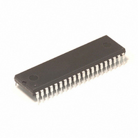
IC MCU 8MHZ 32K FLASH 40-DIP
Manufacturer
Freescale Semiconductor
Series
HC08r
Datasheet
1.MC68HC908GP32CFB.pdf
(410 pages)
Specifications of MC68HC908GP32CP
Core Processor
HC08
Core Size
8-Bit
Speed
8MHz
Connectivity
SCI, SPI
Peripherals
LVD, POR, PWM
Number Of I /o
33
Program Memory Size
32KB (32K x 8)
Program Memory Type
FLASH
Ram Size
512 x 8
Voltage - Supply (vcc/vdd)
2.7 V ~ 5.5 V
Data Converters
A/D 8x8b
Oscillator Type
Internal
Operating Temperature
-40°C ~ 85°C
Package / Case
40-DIP (0.600", 15.24mm)
For Use With
M68EVB908GP32 - BOARD EVALUATION FOR HC908GP32
Lead Free Status / RoHS Status
Contains lead / RoHS non-compliant
Eeprom Size
-
Available stocks
Company
Part Number
Manufacturer
Quantity
Price
Company:

Part Number:
MC68HC908GP32CP
Manufacturer:
ROCKWELL
Quantity:
201
Part Number:
MC68HC908GP32CP
Manufacturer:
MOTOROLA/摩托罗拉
Quantity:
20 000


22.5.3.2 Buffered Output Compare
22.5.4 Pulse Width Modulation (PWM)
MC68HC908GP32
MOTOROLA
NOTE:
•
MC68HC08GP32
Channels 0 and 1 can be linked to form a buffered output compare
channel whose output appears on the TCH0 pin. The TIM channel
registers of the linked pair alternately control the output.
Setting the MS0B bit in TIM channel 0 status and control register (TSC0)
links channel 0 and channel 1. The output compare value in the TIM
channel 0 registers initially controls the output on the TCH0 pin. Writing
to the TIM channel 1 registers enables the TIM channel 1 registers to
synchronously control the output after the TIM overflows. At each
subsequent overflow, the TIM channel registers (0 or 1) that control the
output are the ones written to last. TSC0 controls and monitors the
buffered output compare function, and TIM channel 1 status and control
register (TSC1) is unused. While the MS0B bit is set, the channel 1 pin,
TCH1, is available as a general-purpose I/O pin.
In buffered output compare operation, do not write new output compare
values to the currently active channel registers. User software should
track the currently active channel to prevent writing a new value to the
active channel. Writing to the active channel registers is the same as
generating unbuffered output compares.
By using the toggle-on-overflow feature with an output compare channel,
the TIM can generate a PWM signal. The value in the TIM counter
modulo registers determines the period of the PWM signal. The channel
pin toggles when the counter reaches the value in the TIM counter
modulo registers. The time between overflows is the period of the PWM
signal.
As
registers determines the pulse width of the PWM signal. The time
between overflow and output compare is the pulse width. Program the
TIM to clear the channel pin on output compare if the state of the PWM
pulse is logic 1. Program the TIM to set the pin if the state of the PWM
pulse is logic 0.
Figure 22-3
—
Rev. 6
Timer Interface Module (TIM)
shows, the output compare value in the TIM channel
Timer Interface Module (TIM)
Functional Description
Technical Data
349
Related parts for MC68HC908GP32CP
Image
Part Number
Description
Manufacturer
Datasheet
Request
R

Part Number:
Description:
Manufacturer:
Freescale Semiconductor, Inc
Datasheet:
Part Number:
Description:
Manufacturer:
Freescale Semiconductor, Inc
Datasheet:
Part Number:
Description:
Manufacturer:
Freescale Semiconductor, Inc
Datasheet:
Part Number:
Description:
Manufacturer:
Freescale Semiconductor, Inc
Datasheet:
Part Number:
Description:
Manufacturer:
Freescale Semiconductor, Inc
Datasheet:
Part Number:
Description:
Manufacturer:
Freescale Semiconductor, Inc
Datasheet:
Part Number:
Description:
Manufacturer:
Freescale Semiconductor, Inc
Datasheet:
Part Number:
Description:
Manufacturer:
Freescale Semiconductor, Inc
Datasheet:
Part Number:
Description:
Manufacturer:
Freescale Semiconductor, Inc
Datasheet:
Part Number:
Description:
Manufacturer:
Freescale Semiconductor, Inc
Datasheet:
Part Number:
Description:
Manufacturer:
Freescale Semiconductor, Inc
Datasheet:
Part Number:
Description:
Manufacturer:
Freescale Semiconductor, Inc
Datasheet:
Part Number:
Description:
Manufacturer:
Freescale Semiconductor, Inc
Datasheet:
Part Number:
Description:
Manufacturer:
Freescale Semiconductor, Inc
Datasheet:
Part Number:
Description:
Manufacturer:
Freescale Semiconductor, Inc
Datasheet: