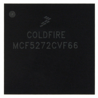
MCF5272CVF66 Freescale Semiconductor, MCF5272CVF66 Datasheet - Page 41

MCF5272CVF66
Manufacturer Part Number
MCF5272CVF66
Description
IC MPU 32BIT 66MHZ 196-MAPBGA
Manufacturer
Freescale Semiconductor
Series
MCF527xr
Specifications of MCF5272CVF66
Core Processor
Coldfire V2
Core Size
32-Bit
Speed
66MHz
Connectivity
EBI/EMI, Ethernet, I²C, SPI, UART/USART, USB
Peripherals
DMA, WDT
Number Of I /o
32
Program Memory Size
16KB (4K x 32)
Program Memory Type
ROM
Ram Size
1K x 32
Voltage - Supply (vcc/vdd)
3 V ~ 3.6 V
Oscillator Type
External
Operating Temperature
-40°C ~ 85°C
Package / Case
196-MAPBGA
Family Name
MCF5xxx
Device Core
ColdFire
Device Core Size
32b
Frequency (max)
66MHz
Instruction Set Architecture
RISC
Supply Voltage 1 (typ)
3.3V
Operating Temp Range
-40C to 85C
Operating Temperature Classification
Industrial
Mounting
Surface Mount
Pin Count
196
Package Type
MA-BGA
Lead Free Status / RoHS Status
Contains lead / RoHS non-compliant
Eeprom Size
-
Data Converters
-
Lead Free Status / Rohs Status
Not Compliant
Available stocks
Company
Part Number
Manufacturer
Quantity
Price
Company:
Part Number:
MCF5272CVF66
Manufacturer:
Freescale Semiconductor
Quantity:
10 000
Part Number:
MCF5272CVF66
Manufacturer:
FREESCALE
Quantity:
20 000
Company:
Part Number:
MCF5272CVF66 K75N
Manufacturer:
ST
Quantity:
18
Company:
Part Number:
MCF5272CVF66J
Manufacturer:
Freescale Semiconductor
Quantity:
10 000
- Current page: 41 of 544
- Download datasheet (7Mb)
Freescale Semiconductor
•
•
•
•
•
•
•
•
•
•
•
•
•
Chapter 5, “Debug
Chapter 6, “System Integration Module
arbitration, power management, and system-protection functions for the MCF5272.
Chapter 7, “Interrupt
Includes descriptions of the registers in the interrupt controller memory map and the interrupt
priority scheme.
Chapter 8, “Chip Select
the operation and programming model, which includes the chip-select address, mask, and control
registers.
Chapter 9, “SDRAM
DRAM controller component of the SIM, including a general description of signals involved in
SDRAM operations. It provides interface information for memory configurations using most
common SDRAM devices for both 16- and 32-bit-wide data buses. The chapter concludes with
signal timing diagrams.
Chapter 10, “DMA
controller intended for memory-to-memory block data transfers. This chapter describes in detail its
signals, registers, and operating modes.
Chapter 11, “Ethernet
(MAC). This chapter begins with a feature-set overview, a functional block diagram, and
transceiver connection information for both MII and seven-wire serial interfaces. The chapter
concludes with detailed descriptions of operation and the programming model.
Chapter 12, “Universal Serial Bus
MCF5272, including detailed operation information and the USB programming model.
Connection examples and circuit board layout considerations are also provided.
The USB Specification, Revision 1.1 is a recommended supplement to this chapter. It can be
downloaded from http://www.usb.org. Chapter 2 of this specification, Terms and Abbreviations,
provides definitions of many of the words found here.
Chapter 13, “Physical Layer Interface Controller
MCF5272’s physical layer interface controller, a module intended to support ISDN applications.
The chapter begins with a description of operation and a series of related block diagrams starting
with a high-level overview. Each successive diagram depicts progressively more internal detail.
The chapter then describes timing generation and the programming model and concludes with
three application examples.
Chapter 14, “Queued Serial Peripheral Interface (QSPI)
and description of operation, including details of the QSPI’s internal RAM organization. The
chapter concludes with the programming model and a timing diagram.
Chapter 15, “Timer
timer modules, timer 0, 1, 2 and 3.
Chapter 16, “UART
receiver/transmitters (UARTs) implemented on the MCF5272, including example register values
for typical configurations.
MCF5272 ColdFire
Support,” describes the Revision A hardware debug support in the MCF5272.
Controller,” provides an overview of the MCF5272’s one-channel DMA
Module,” describes configuration and operation of the four general-purpose
Modules,” describes the use of the universal asynchronous/synchronous
Controller,” describes operation of the interrupt controller portion of the SIM.
Controller,” describes configuration and operation of the synchronous
Module,” describes the MCF5272 fast Ethernet media access controller
Module,” describes the MCF5272 chip-select implementation, including
®
Integrated Microprocessor User’s Manual, Rev. 3
(USB),” provides an overview of the USB module of the
(SIM),” describes the SIM programming model, bus
(PLIC),” provides detailed information about the
Module,” provides a feature-set overview
xli
Related parts for MCF5272CVF66
Image
Part Number
Description
Manufacturer
Datasheet
Request
R
Part Number:
Description:
Mcf5272 Coldfire Integrated Microprocessor User
Manufacturer:
Freescale Semiconductor, Inc
Datasheet:

Part Number:
Description:
MCF5272 Interrupt Service Routine for the Physical Layer Interface Controller
Manufacturer:
Freescale Semiconductor / Motorola
Datasheet:
Part Number:
Description:
Manufacturer:
Freescale Semiconductor, Inc
Datasheet:
Part Number:
Description:
Manufacturer:
Freescale Semiconductor, Inc
Datasheet:
Part Number:
Description:
Manufacturer:
Freescale Semiconductor, Inc
Datasheet:
Part Number:
Description:
Manufacturer:
Freescale Semiconductor, Inc
Datasheet:
Part Number:
Description:
Manufacturer:
Freescale Semiconductor, Inc
Datasheet:
Part Number:
Description:
Manufacturer:
Freescale Semiconductor, Inc
Datasheet:
Part Number:
Description:
Manufacturer:
Freescale Semiconductor, Inc
Datasheet:
Part Number:
Description:
Manufacturer:
Freescale Semiconductor, Inc
Datasheet:
Part Number:
Description:
Manufacturer:
Freescale Semiconductor, Inc
Datasheet:
Part Number:
Description:
Manufacturer:
Freescale Semiconductor, Inc
Datasheet:
Part Number:
Description:
Manufacturer:
Freescale Semiconductor, Inc
Datasheet:
Part Number:
Description:
Manufacturer:
Freescale Semiconductor, Inc
Datasheet:
Part Number:
Description:
Manufacturer:
Freescale Semiconductor, Inc
Datasheet:


