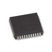
XR88C681J-F Exar Corporation, XR88C681J-F Datasheet - Page 66

XR88C681J-F
Manufacturer Part Number
XR88C681J-F
Description
IC UART CMOS DUAL 44PLCC
Manufacturer
Exar Corporation
Type
CMOS Dual Channel UARTr
Datasheet
1.XR88C681CP40-F.pdf
(101 pages)
Specifications of XR88C681J-F
Number Of Channels
2, DUART
Package / Case
44-LCC (J-Lead)
Features
*
Fifo's
1 Byte, 3 Byte
Voltage - Supply
5V
With Parallel Port
Yes
With Cmos
Yes
Mounting Type
Surface Mount
Data Rate
1 Mbps
Supply Voltage (max)
5.25 V
Supply Voltage (min)
4.75 V
Supply Current
15 mA
Maximum Operating Temperature
+ 85 C
Minimum Operating Temperature
- 40 C
Mounting Style
SMD/SMT
Operating Supply Voltage
5 V
Propagation Delay Time Ns
400 ns
No. Of Channels
2
Supply Voltage Range
4.75V To 5.25V
Operating Temperature Range
-40°C To +85°C
Digital Ic Case Style
PLCC
No. Of Pins
44
Filter Terminals
SMD
Rohs Compliant
Yes
Lead Free Status / RoHS Status
Lead free / RoHS Compliant
Lead Free Status / RoHS Status
Lead free / RoHS Compliant, Lead free / RoHS Compliant
Other names
1016-1329
Available stocks
Company
Part Number
Manufacturer
Quantity
Price
Company:
Part Number:
XR88C681J-F
Manufacturer:
Exar Corporation
Quantity:
10 000
In summary, for the “SET OUTPUT PORT BITS”
command;
Dn = 0; results in no change for OPR[n], nor Output Port
pin OPn.
Dn = 1; results in OPR[n] = “1”, and Output Port pin, OPn =
“0”
F.1.2 Clear Output Port Bits Command
The procedure for invoking this command is very similar
to that for “SET OUTPUT PORT BITS COMMAND”;
except in that the user now writes to DUART address 0F
for [OP7,...,OP0].
For every “1” that is “written” to this address, the
corresponding bit in the OPR register is set to a logic “low”
and the corresponding Output Port pin, OPn is set to a
logic “high”. For every “0” that is written to this address,
In summary, for the “CLEAR OUTPUT PORT BITS”
command;
Dn = 0, results in no change for OPR[n] and no change in
the state of the Output Port pin, OPn.
Rev. 2.11
Data Bus, D7 - D0
Initial OPR [7:0]
Final OPR [7:0]
Figure 34. Illustration of the “CLEAR OUTPUT PORT BIT” Command and its Effect
on the Output Port Register and the State of the Output Port Pins.
1
1
0
1
0
1
1
0
1
1
0
1
1
1
0
1
1
0
0
1
1
16
1
1
0
66
the state of the corresponding OPR register bit, and in
turn the state of the Output Port pin is unchanged.
For Example:
Suppose that the contents of the Output Port Register,
OPR = [1, 1, 1, 1, 1, 1, 1, 1]. Consequently, the state of the
Output Port pins are:
[OP7, OP6, OP5, OP4, OP3, OP2, OP1, OP0] = [0, 0, 0, 0,
0, 0, 0, 0]
DUART address 0F16, the resulting contents of the
Output Port register will be:
OPR[7:0] = [0, 0, 0, 0, 1, 1, 1, 1]
Further, the resulting state of the Output Port pins will be:
[OP7, OP6, OP5, OP4, OP3, OP2, OP1, OP0] = [1, 1, 1, 1,
0, 0, 0, 0]
This example of the “SET OUTPUT PORT BITS”
command is illustrated in Figure 34.
Dn = 1, results in OPR[n] = 0, and sets the corresponding
Output Port pin to a logic “1”.
If we were to write [D7,...,D0] = [1, 1, 1, 1, 0, 0, 0, 0] to
State of the Output Port Pins (OP7-OP0)
0
1
1
0
DUART Address 0Fh
0
1
0
1
0
0
0
0
0
0
0
0


