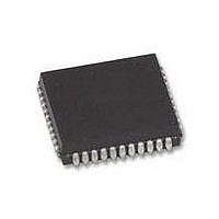
XR88C681J-F Exar Corporation, XR88C681J-F Datasheet - Page 83

XR88C681J-F
Manufacturer Part Number
XR88C681J-F
Description
IC UART CMOS DUAL 44PLCC
Manufacturer
Exar Corporation
Type
CMOS Dual Channel UARTr
Datasheet
1.XR88C681CP40-F.pdf
(101 pages)
Specifications of XR88C681J-F
Number Of Channels
2, DUART
Package / Case
44-LCC (J-Lead)
Features
*
Fifo's
1 Byte, 3 Byte
Voltage - Supply
5V
With Parallel Port
Yes
With Cmos
Yes
Mounting Type
Surface Mount
Data Rate
1 Mbps
Supply Voltage (max)
5.25 V
Supply Voltage (min)
4.75 V
Supply Current
15 mA
Maximum Operating Temperature
+ 85 C
Minimum Operating Temperature
- 40 C
Mounting Style
SMD/SMT
Operating Supply Voltage
5 V
Propagation Delay Time Ns
400 ns
No. Of Channels
2
Supply Voltage Range
4.75V To 5.25V
Operating Temperature Range
-40°C To +85°C
Digital Ic Case Style
PLCC
No. Of Pins
44
Filter Terminals
SMD
Rohs Compliant
Yes
Lead Free Status / RoHS Status
Lead free / RoHS Compliant
Lead Free Status / RoHS Status
Lead free / RoHS Compliant, Lead free / RoHS Compliant
Other names
1016-1329
Available stocks
Company
Part Number
Manufacturer
Quantity
Price
Company:
Part Number:
XR88C681J-F
Manufacturer:
Exar Corporation
Quantity:
10 000
Figure 44 shows two DUART devices, one labeled
“Transmitting Device” and the other, “Receiving Device”.
This example starts with the assumption that the
“Transmitter Device” has been programmed such that
MR2A[5] = 1, which results in programming the
“Transmitting Device” for Transmitter-RTS Control. This
example further assumes that the “Transmitting Device”
has been programmed such that MR2A[4] = 1. According
to Section G.3, the Transmitter of Channel A of the
“Transmitting Device” has now been programmed to be
under -CTSA input control.
In the case of the “Receiving Device”, IP2 (RTS-in) has
been programmed to generate an “Input Port Change of
State” interrupt request to the CPU. The firmware for the
Interrupt Service Routines is written such that if the IP2
input were to change and IPCR[2] = 0, the CPU would
“write” [D7,..., D0] = [0, 0, 0, 0, 1, 0, 0, 0] to DUART
address 0E
would
COMMAND”, and in the process toggle OPR[3] to a logic
“high” and the Output Port pin, OP3, (CTS-out) to a logic
“low”. This would, in turn, assert the -CTSA input of the
Rev. 2.11
invoke
16
. In this step, the Interrupt Service Routine
the
“SET
OUTPUT
PORT
BITS
83
“Transmitting Device” and allow it to transmit data to the
“Receiving Device”.
Once Channel A Transmitter has emptied both its THR
and TSR of data, it will negate the -RTSA output, via the
“Transmitter-RTS Control” feature. When the -RTSA
output the “Transmitting Device” is toggled “high”, the IP2
(RTS-in) is also toggled “high”, thereby generating
another “Input Change of State” interrupt request to the
CPU.
Routine would be to “Write” [D7,..., D0] = [0, 0, 0, 0, 1, 0, 0,
0] to DUART address 0F
Service Routine would invoke the “CLEAR OUTPUT
PORT BITS COMMAND”, and in the process toggle OP3
(CTS-out) “high”. This would in turn negate the -CTSA
input of the “Transmitting Device” and inhibit the
transmission of data from the Channel A of the
“Transmitting Device”.
Figure 45 presents a Flow Diagram which depicts an
Algorithm that could be used to implement the
Transmitter-Control
Please note that the shaded block pertain to occurrences
within the “Receiving Device”. Whereas the “White” block
pertain to operation within the “Transmitting Device.”
With IPCR[2] = 1, the likely Interrupt Service
RTS/CTS
16
. In this step, the Interrupt
XR88C681
Handshaking
Mode.


