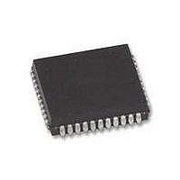
XR88C681J-F Exar Corporation, XR88C681J-F Datasheet - Page 87

XR88C681J-F
Manufacturer Part Number
XR88C681J-F
Description
IC UART CMOS DUAL 44PLCC
Manufacturer
Exar Corporation
Type
CMOS Dual Channel UARTr
Datasheet
1.XR88C681CP40-F.pdf
(101 pages)
Specifications of XR88C681J-F
Number Of Channels
2, DUART
Package / Case
44-LCC (J-Lead)
Features
*
Fifo's
1 Byte, 3 Byte
Voltage - Supply
5V
With Parallel Port
Yes
With Cmos
Yes
Mounting Type
Surface Mount
Data Rate
1 Mbps
Supply Voltage (max)
5.25 V
Supply Voltage (min)
4.75 V
Supply Current
15 mA
Maximum Operating Temperature
+ 85 C
Minimum Operating Temperature
- 40 C
Mounting Style
SMD/SMT
Operating Supply Voltage
5 V
Propagation Delay Time Ns
400 ns
No. Of Channels
2
Supply Voltage Range
4.75V To 5.25V
Operating Temperature Range
-40°C To +85°C
Digital Ic Case Style
PLCC
No. Of Pins
44
Filter Terminals
SMD
Rohs Compliant
Yes
Lead Free Status / RoHS Status
Lead free / RoHS Compliant
Lead Free Status / RoHS Status
Lead free / RoHS Compliant, Lead free / RoHS Compliant
Other names
1016-1329
Available stocks
Company
Part Number
Manufacturer
Quantity
Price
Company:
Part Number:
XR88C681J-F
Manufacturer:
Exar Corporation
Quantity:
10 000
Receiver Operation During Multi-Drop Mode
When a channel has been programmed into the
Multi-Drop Mode, and the Receiver has been disabled (a
typical configuration), the Receiver will load a character
into the RHR and set the RXRDY indicator (and/or
interrupt) if the A/D bit is “1” (Address flag). However, the
character will be discarded if its A/D bit is “0” (Data flag).
Therefore, in response to the RXRDY indicator, the CPU
should then read the received character and determine if
the address that it represents matches that of the CPU. If
the Addresses do match, (indicating that it is the Target
Slave), then the CPU should enable the Receiver, in
preparation for the subsequent blocks of data.
Once the Receiver has been enabled the Receiver Serial
Data will be processed as in Normal Operation. The
Rev. 2.11
Figure 49. A Flow Diagram Depicting a Procedure That Can Be Used to Receive
No
Character from RHRn
Channel is Commanded
into Multi-Drop Mode.
Receiver is Disabled
MR1n[4:3] = [1, 1]
RXRDY Indicator
Read in Address
been asserted
START
Has
?
Yes
Characters in the Multi-Drop Mode.
No
Read in Data Character
87
Appropriate Channel
Command Register)
(Write x2h to the
Enable Receiver
Newly Received
Address match
CPU Address
New Character a
received characters are accessible to the CPU by reading
the RHR. The state of the A/D flag bit is available at
SRn[5], the Status Register bit normally used to indicate
“Parity Error”. Therefore, in conjunction with receiver
each new character, the CPU should continue to monitor
SRn[5] in order to verify that it is a “0” (Data characters).
Once the “Target CPU” detects a new address character,
SRn[5] =“1”, it should compare this address with its own.
If the addresses do not match, then this CPU is not the
intended recipient of the next block of data, and now
should disable the Receiver. Figure 49 presents a flow
diagram depicting a recommended procedure for
handling received characters while in the Multi-Drop
Mode.
Data Character
Check SRn[5]
from RHR.
SRn[5] = 1?
Does
Is the
?
Yes
No
Yes
Receiver remains Disabled
XR88C681
Reject Character


