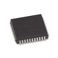
XR88C681J-F Exar Corporation, XR88C681J-F Datasheet - Page 72

XR88C681J-F
Manufacturer Part Number
XR88C681J-F
Description
IC UART CMOS DUAL 44PLCC
Manufacturer
Exar Corporation
Type
CMOS Dual Channel UARTr
Datasheet
1.XR88C681CP40-F.pdf
(101 pages)
Specifications of XR88C681J-F
Number Of Channels
2, DUART
Package / Case
44-LCC (J-Lead)
Features
*
Fifo's
1 Byte, 3 Byte
Voltage - Supply
5V
With Parallel Port
Yes
With Cmos
Yes
Mounting Type
Surface Mount
Data Rate
1 Mbps
Supply Voltage (max)
5.25 V
Supply Voltage (min)
4.75 V
Supply Current
15 mA
Maximum Operating Temperature
+ 85 C
Minimum Operating Temperature
- 40 C
Mounting Style
SMD/SMT
Operating Supply Voltage
5 V
Propagation Delay Time Ns
400 ns
No. Of Channels
2
Supply Voltage Range
4.75V To 5.25V
Operating Temperature Range
-40°C To +85°C
Digital Ic Case Style
PLCC
No. Of Pins
44
Filter Terminals
SMD
Rohs Compliant
Yes
Lead Free Status / RoHS Status
Lead free / RoHS Compliant
Lead Free Status / RoHS Status
Lead free / RoHS Compliant, Lead free / RoHS Compliant
Other names
1016-1329
Available stocks
Company
Part Number
Manufacturer
Quantity
Price
Company:
Part Number:
XR88C681J-F
Manufacturer:
Exar Corporation
Quantity:
10 000
MR1n[7] - Receiver Request to Send Control
Ordinarily, RTS (Request to Send) is asserted or negated
by invoking the “SET OUTPUT PORT BITS COMMAND”
or “CLEAR OUTPUT PORT BITS COMMAND” in the
appropriate manner. However, if MR1n[7] = 1 is set, then
the Receiver will have control over the negation of the
-RTSn output. Specifically, setting this bit will allow the
Receiver to negate -RTSn if its RHR is full. This “flow
control” technique is useful in preventing Receiver
Overrun Errors.
Figure 42 presents a diagram which illustrates how a
Receiver-Controlled
would function.
MR1n[6] - Receiver Interrupt Select
This bit selects either the RXRDY status bit or the FFULL
status bit of the channel to be used as the criteria for
generating an Interrupt Request to the CPU, ISR[1] for
Channel A and ISR[5] for Channel B.
MR1n[5] - Error Mode Select
This bit controls the operation of the three FIFO status bits
(PE, FE, Received Break) for the Channel. If this bit is set
to “0”, this particular channel will operate in the
“Character” Error Mode. If this bits is set to “1”, this
particular channel will operate in the “Block” Error Mode.
In the character mode these status bits apply only to the
character that is currently at the top of the FIFO. In the
block mode, these bits represent the cumulative logical
Rev. 2.11
Bit 7
11 = Remote Loop
10 = Local Loop
01 = Auto Echo
Channel Mode
00 = Normal
Bit 6
Request-to-Send
Tx RTS
Control
1 = Yes
0 = No
Bit 5
Table 27. Mode Registers - MR2A, MR2B
configuration
CTS Enable
1 = Yes
0 = No
Bit 4
Tx
72
OR of the status for all characters coming to the top of the
FIFO since the last “RESET ERROR STATUS” command
for the Channel was issued.
MR1n[4:3] - Parity Mode Select
If “with parity” or “force parity” operation is programmed, a
parity bit is added to the transmitted characters and the
receiver performs a parity check on received characters.
See Section H.2 for description of Multi-Drop Mode
Operation.
MR1n[2] - Parity Type Select
This bit selects ODD or EVEN parity if “WITH PARITY
MODE” is programmed and the state of the forced parity
bit if the “FORCE PARITY” mode is programmed. In the
Multi-Drop mode it selects the state of the A/D flag bit.
This bit has no effect if “NO PARITY” is selected in
MR1n[4:3].
MR1n[1:0] - Bits per Character Select
Selects the number of bits to be transmitted and received
in the data field of the character. This does not include
START, PARITY, and STOP bits.
Mode Register 2 (Channels A and B)
MR2n for each Channel is accessed when the Channel’s
MR Pointer points to MR2n, which occurs after any
access to the Channel’s MR1 Register. Subsequent
“reads” or “writes” to MR2n does not change the contents
of the MR pointer.
Bit 3
0 = 0.563
1 = 0.625
2 = 0.688
3 = 0.750
4 = 0.813
5 = 0.875
6 = 0.938
7 = 1.000
Bit 2
Bit Length
Bit 1
C = 1.813
D = 1.875
A = 1.688
B = 1.750
E = 1.938
F = 2.000
8 = 1.563
9 = 1.625
Bit 0


