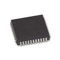
XR88C681J-F Exar Corporation, XR88C681J-F Datasheet - Page 74

XR88C681J-F
Manufacturer Part Number
XR88C681J-F
Description
IC UART CMOS DUAL 44PLCC
Manufacturer
Exar Corporation
Type
CMOS Dual Channel UARTr
Datasheet
1.XR88C681CP40-F.pdf
(101 pages)
Specifications of XR88C681J-F
Number Of Channels
2, DUART
Package / Case
44-LCC (J-Lead)
Features
*
Fifo's
1 Byte, 3 Byte
Voltage - Supply
5V
With Parallel Port
Yes
With Cmos
Yes
Mounting Type
Surface Mount
Data Rate
1 Mbps
Supply Voltage (max)
5.25 V
Supply Voltage (min)
4.75 V
Supply Current
15 mA
Maximum Operating Temperature
+ 85 C
Minimum Operating Temperature
- 40 C
Mounting Style
SMD/SMT
Operating Supply Voltage
5 V
Propagation Delay Time Ns
400 ns
No. Of Channels
2
Supply Voltage Range
4.75V To 5.25V
Operating Temperature Range
-40°C To +85°C
Digital Ic Case Style
PLCC
No. Of Pins
44
Filter Terminals
SMD
Rohs Compliant
Yes
Lead Free Status / RoHS Status
Lead free / RoHS Compliant
Lead Free Status / RoHS Status
Lead free / RoHS Compliant, Lead free / RoHS Compliant
Other names
1016-1329
Available stocks
Company
Part Number
Manufacturer
Quantity
Price
Company:
Part Number:
XR88C681J-F
Manufacturer:
Exar Corporation
Quantity:
10 000
In this mode:
1. Received data is transmitted on the channel’s TXD
2. The receiver must be enabled but the transmitter need
3. The channel’s TXRDY and TXEMT status bits are
4. The received parity is checked but is not generated for
5. Character framing is checked but the stop bits are
output.
not be enabled.
inactive.
transmission. Thus, transmitted parity is as received.
transmitted as received.
Rev. 2.11
Incoming
Serial Data
Receive Holding
Register
RXDn
(To be read by the CPU)
Figure 39. A Block Diagram Depict Automatic Echo Mode
Receive Shift Register
To Data Bus
8
RXCn
74
6. A received break is echoed as received until the next
7. CPU to receiver communications operates normally,
Each DUART channel can be configured into one of two
diagnostic modes.
Local Loopback Mode
This mode is selected by setting MR2n[7:6] = 10.
Figure 40 is a diagram depicting Local Loopback Mode
operation.
TXCn
valid start bit is detected.
but the CPU to transmitter link is disabled.
Transmit Shift Register
CPU has no access to
the Transmitter
TXDn
Transmit Holding
Register
Outgoing Serial
Data


