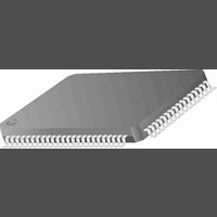
CR16MCS9VJE8 National Semiconductor, CR16MCS9VJE8 Datasheet - Page 37

CR16MCS9VJE8
Manufacturer Part Number
CR16MCS9VJE8
Description
16-Bit Microcontroller IC
Manufacturer
National Semiconductor
Datasheet
1.CR16MCS9VJE8.pdf
(156 pages)
Specifications of CR16MCS9VJE8
Controller Family/series
CR16X
Core Size
16 Bit
Program Memory Size
64K X 8 Flash
Digital Ic Case Style
PQFP
No. Of Pins
80
Mounting Type
Surface Mount
Clock Frequency
25MHz
Lead Free Status / RoHS Status
Contains lead / RoHS non-compliant
Available stocks
Company
Part Number
Manufacturer
Quantity
Price
Company:
Part Number:
CR16MCS9VJE8
Manufacturer:
ON
Quantity:
8 917
Company:
Part Number:
CR16MCS9VJE8-CBB
Manufacturer:
ON
Quantity:
846
Company:
Part Number:
CR16MCS9VJE8-CBC
Manufacturer:
ON
Quantity:
109
Company:
Part Number:
CR16MCS9VJE8-CBD
Manufacturer:
ON
Quantity:
17
Company:
Part Number:
CR16MCS9VJE8-CBE
Manufacturer:
ON
Quantity:
1 950
Some of the power-up transitions are based on the occur-
rence of a wake-up event. An event of this type can be either
a maskable interrupt or a non-maskable interrupt (NMI). All
of the maskable hardware wake-up events are gathered and
processed by the Multi-Input Wake-Up Module, which is ac-
tive in all modes. Once a wake-up event is detected, it is
latched until an interrupt acknowledge cycle occurs or a reset
is applied.
A wake-up event causes a transition to the Active mode and
restores normal clock operation, but does not start execution
of the program. It is the interrupt service routine associated
with the wake-up source (MIWU16 or NMI) that causes actu-
al program execution to resume.
11.6.1
The Power Management Control/Status Register (PMCSR)
is a byte-wide, read/write register that controls the operating
power mode (Active, Power Save, Idle, or Halt) and enables
or disables the high-frequency oscillator in the Power Save
and Idle modes. The two most significant bits, OLFC and
OHFC, are read-only status bits controlled by the hardware.
Upon reset, the non-reserved bits of this register are cleared.
The format of the register is shown below.
PSM
DHF
and WAIT
7
OLFC OHFC WBPSM Reserved HALT IDLE DHF PSM
HALT =1
6
Reset
Figure 6.
Power Management Control/Status Register
(PMCSR)
Power Save Mode. When this bit is 0, the de-
vice operates in the Active mode. Writing a 1 to
this bit position puts the device into the Power
Save mode, either immediately or upon execu-
tion of the next WAIT instruction, depending on
the WBPSM bit.
The PSM bit can be set and cleared by the soft-
ware. It is also cleared by the hardware when a
hardware wake-up event is detected.
Disable High-Frequency Oscillator. This bit en-
ables (0) or disables (1) the high-frequency os-
cillator in the Power Save or Idle mode. (The
high-frequency oscillator is always enabled in
Active mode and always disabled in Halt mode,
regardless of this bit settings.) The DHF bit is
cleared automatically when a hardware wake-
up event is detected.
5
Power Modes and Transitions
4
and WAIT
IDLE =1
PSM =1
Power Save
Active
Halt
Idle
3
HW event
or PSM =0
2
HW event
HW event
1
0
37
IDLE
HALT
WBPSM
OHFC
OLFC
Idle Mode. When this bit is set and the device
is in Power Save mode, the device enters the
Idle mode upon execution of a WAIT instruc-
tion. In order to enter the Idle mode directly
from the Active mode, the WBPSM bit must be
set before the WAIT instruction is executed.
The IDLE bit can be set and cleared by the soft-
ware. When a hardware wake-up event is de-
tected, this bit is cleared automatically and the
device returns to the Active mode.
Halt Mode. When this bit is set and the device
is in Idle mode, the device enters the Halt mode
upon execution of a WAIT instruction. In order
to enter the Halt mode directly from the Active
mode, the WBPSM bit must be set before the
WAIT instruction is executed.
The Halt bit can be set and cleared by the soft-
ware. When a hardware wake-up event is de-
tected, this bit is cleared automatically and the
device returns to the Active mode.
Wait Before Entering Power Save Mode. When
the CPU writes a 1 to the PSM bit, the WBPSM
determines when the transition from Active to
Power Save mode is done. If the WBPSM bit is
0, the switch to Power Save mode is initiated
immediately; the PSM bit in the register is set
to 1 upon completion of the switch to Power
Save mode. If the WBPSM bit is 1, the device
continues to operate in Active mode until the
next WAIT instruction, and then enters the
Power Save mode. In this case, the PSM bit is
set to 1 immediately, even if a WAIT instruction
has not yet been executed.
In the Active mode, the WBPSM bit must be set
in order to enter the Idle or Halt mode.
Oscillating High-Frequency Clock. This read-
only bit indicates the status of the high-frequen-
cy clock. If this bit is 1, the high-frequency clock
is available and stable. If this bit is 0, the high-
frequency clock is either disabled, not available
to the Power Management Module, or operat-
ing but not yet stable. The device can switch to
the Active mode only when this bit is 1.
Oscillating Low-Frequency Clock. This read-
only bit indicates the status of the low-frequen-
cy (slow) clock. If this bit is 1, it indicates that
the slow clock is running and stable. The slow
clock can be either the prescaled fast clock (the
default) or the external oscillator (if selected).
The Dual Clock module will not allow a transi-
tion to the slow crystal mode unless the slow
crystal is operating, so this bit should be 1 un-
der normal circumstances.
The device can switch from the Active mode to
the Power Save or Idle mode only if the OLFC
bit is 1. There is no such restriction on switch-
ing to the Halt mode.
www.national.com


