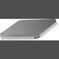
CR16MCS9VJE8 National Semiconductor, CR16MCS9VJE8 Datasheet - Page 94

CR16MCS9VJE8
Manufacturer Part Number
CR16MCS9VJE8
Description
16-Bit Microcontroller IC
Manufacturer
National Semiconductor
Datasheet
1.CR16MCS9VJE8.pdf
(156 pages)
Specifications of CR16MCS9VJE8
Controller Family/series
CR16X
Core Size
16 Bit
Program Memory Size
64K X 8 Flash
Digital Ic Case Style
PQFP
No. Of Pins
80
Mounting Type
Surface Mount
Clock Frequency
25MHz
Lead Free Status / RoHS Status
Contains lead / RoHS non-compliant
Available stocks
Company
Part Number
Manufacturer
Quantity
Price
Company:
Part Number:
CR16MCS9VJE8
Manufacturer:
ON
Quantity:
8 917
Company:
Part Number:
CR16MCS9VJE8-CBB
Manufacturer:
ON
Quantity:
846
Company:
Part Number:
CR16MCS9VJE8-CBC
Manufacturer:
ON
Quantity:
109
Company:
Part Number:
CR16MCS9VJE8-CBD
Manufacturer:
ON
Quantity:
17
Company:
Part Number:
CR16MCS9VJE8-CBE
Manufacturer:
ON
Quantity:
1 950
www.national.com
20.2.3
In the Bit Time Logic (BTL), the CAN bus speed and the Syn-
chronization Jump Width can be configured by the user.
The time segment 1 includes the propagation segment and
the phase segment 1 as specified in the CAN specification
2.0.B. The length of the time segment 1 in time quantas (tq)
is defined by the TSEG1[3:0] bits.
The time segment 2 represents the phase segment 2 as
specified in the CAN specification 2.0.B. The length of the
time segment 2 in time quantas (tq) is defined by the
TSEG2[2:0] bits.
The Synchronization Jump Width (SJW) defines the max-
imum number of time quanta (tq) by which a received CAN
bit can be shortened or lengthened in order to achieve re-
synchronization on ‘recessive’ to ‘dominant’ data transitions
on the bus. In the CR16CAN implementation the SJW has to
be configured less or equal to TSEG1 or TSEG2, whatever is
smaller.
Synchronization
A CAN device expects the transition of the data signal to be
within the synchronization segment of each CAN bit time.
This segment has the fixed length of one time quantum.
However, two CAN nodes never operate at exactly the same
clock rate and furthermore the bus signal may deviate from
the ideal waveform due to the physical conditions of the net-
work (bus length and load). In order to compensate for the
various delays within a network, the sample point can be po-
sitioned by programming the length of time segments 1 and
2 (see Figure52).
In addition to that, two types of synchronization are support-
ed. The BTL logic compares the incoming edge of a CAN bit
— If only one device is on the bus and this device trans-
mits a message, it will get no acknowledgment. This
will be detected as an error and the message will be re-
peated. When the device goes ‘error passive’ and de-
tects an acknowledge error, the TEC counter is not
incremented. Therefore the device will not go from ‘er-
ror passive’ to the ‘bus off’ state due to such a condi-
tion.
Bit Time Logic
ONE TIME QUANTUM
A = synchronization segment (Sync)
1 tq
A
TIME SEGMENT 1 (TSEG1)
2 to 16 tq
Figure 52. Bit Timing
4 to 25 tq
94
CR16CAN divides a nominal bit time into three time seg-
ments: synchronization segment, time segment 1 (TSEG1)
and time segment 2 (TSEG2). Figure52 shows the various
elements of a CAN bit time.
CAN Bit Time
The number of time quanta in a CAN bit (CAN Bit Time) lies
between 4 and 25. The sample point is positioned between
TSEG1 and TSEG2 and the transmission point is positioned
at the end of TSEG2.
with the internal bit timing. The internal bit timing can be
adapted by either hard or soft synchronization (re-synchroni-
zation).
Hard synchronization is done at the beginning of a new
frame with the falling edge on the bus while the bus is idle.
This is interpreted as the SOF. It restarts the internal logic.
Soft synchronization is used during the reception of a bit
stream to lengthen or shorten the internal bit time. Depending
on the phase error (e), the time segment 1 may be increased
or the time segment 2 may be decreased by a specific value,
the re-synchronization jump width (SJW).
The phase error is given by the deviation of the edge to the
SYNC segment, measured in CAN clocks. The value of the
phase error is defined as:
Re-synchronization is performed according to the following
rules:
• If the magnitude of e is less or equal to the programmed
• If e > SJW, the time segment 1 will be lengthened by the
• If e < -SJW, the time segment 2 will be shortened by the
value of SJW, re-synchronization will have the same effect
as hard synchronization.
value of the SJW (see Figure53).
value SJW (see Figure 54).
e = 0, if the edge occurs within the SYNC segment.
e > 0, if the edge occurs within TSEG1
e < 0, if the edge occurs within TSEG2 of the previous bit.
SAMPLE
POINT
TIME SEGMENT 2 (TSEG2)
1 to 8 tq
TRANSMISSION
TIME QUANTA
INTERNAL
CLOCK
POINT


