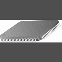
CR16MCS9VJE8 National Semiconductor, CR16MCS9VJE8 Datasheet - Page 69

CR16MCS9VJE8
Manufacturer Part Number
CR16MCS9VJE8
Description
16-Bit Microcontroller IC
Manufacturer
National Semiconductor
Datasheet
1.CR16MCS9VJE8.pdf
(156 pages)
Specifications of CR16MCS9VJE8
Controller Family/series
CR16X
Core Size
16 Bit
Program Memory Size
64K X 8 Flash
Digital Ic Case Style
PQFP
No. Of Pins
80
Mounting Type
Surface Mount
Clock Frequency
25MHz
Lead Free Status / RoHS Status
Contains lead / RoHS non-compliant
Available stocks
Company
Part Number
Manufacturer
Quantity
Price
Company:
Part Number:
CR16MCS9VJE8
Manufacturer:
ON
Quantity:
8 917
Company:
Part Number:
CR16MCS9VJE8-CBB
Manufacturer:
ON
Quantity:
846
Company:
Part Number:
CR16MCS9VJE8-CBC
Manufacturer:
ON
Quantity:
109
Company:
Part Number:
CR16MCS9VJE8-CBD
Manufacturer:
ON
Quantity:
17
Company:
Part Number:
CR16MCS9VJE8-CBE
Manufacturer:
ON
Quantity:
1 950
17.5.2
Upon reset, all non-reserved bits are cleared to 0. The regis-
ter format is shown below.
MEN
MMNS
MMOD
1 5
MCDV
[6:0]
9
MIDL MSKM MEIW MEIR MEIO MECH MMOD MMNS MEN
8
MICROWIRE Control Register (MWCTL)
MICROWIRE Enable. This bit enables (1) or
disables (0) the MICROWIRE interface mod-
ule. Clearing this bit disables the module,
clears the status bits in the MICROWIRE status
register (the MBSY, MRBF, and MOVR flags in
MWSTAT), and places the MICROWIRE inter-
face pins in the states described in Table18.
MICROWIRE Master/Slave Select. When
cleared to 0, the device operates as a slave.
When set to 1, the device operates as the mas-
ter.
MICROWIRE Mode Select (8- or 16-bit). When
set to 0, the device operates in 8-bit mode.
When set to 1, the device operates in 16-bit
mode. This bit should only be changed when
the module is disabled or the MICROWIRE in-
terface is idle (MWSTAT.MBSY=0).
7
MSK
MCS
MDIDO
MDODI
Table 18 Pin Values with MICROWIRE
write
read
DIN
6
5
Read Buffer
Shift Register
4
Master: MnIDL Bit
Slave: input
Input
Master: input
Slave: TRI-STATE
Master: known Value
Slave: input
Disabled
(store)
Low-Byte
3
Low-Byte
Figure 31.
2
(store & MWMOD)
1
MWDAT Register Structure
0
69
MECH
MEIO
MEIR
MEIW
MSKM
High-Byte
High-Byte
MICROWIRE Echo Back. This bit enables (1)
or disables (0) the echo back function in slave
mode. This bit should be written only when the
MICROWIRE interface is idle (MWSTAT.MB-
SY=0). The MECH bit is ignored in master
mode. The MWDAT register is valid from the
time the register has been written until the end
of the transfer.
In the echo back mode, MDODI is transmitted
(echoed back) on MDIDO if MWDAT does not
contain any valid data. With the echo back
function disabled, the data held in the MWDAT
register is transmitted on MDIDO, whether or
not the data is valid.
MICROWIRE Enable Interrupt on Overrun.
This bit enables or disables the overrun error
interrupt. When set to 1, an interrupt is gener-
ated when the Receive Overrun Error flag
(MWSTAT.MOVR) is set. Otherwise, no inter-
rupt is generated when an overrun error oc-
curs. This bit should only be enabled in master
mode.
MICROWIRE Enable Interrupt for Read. When
set to 1, an interrupt is generated when the
Read Buffer Full flag (MWSTAT.MRBF) is set.
Otherwise, no interrupt is generated when the
read buffer is full.
MICROWIRE Enable Interrupt for Write. When
set to 1, an interrupt is generated when the
Busy bit (MWSTAT.MBSY) is cleared, which in-
dicates that a data transfer sequence has been
completed and the read buffer is ready to re-
ceive the new data. Otherwise, no interrupt is
generated when the Busy bit is cleared.
MICROWIRE Clocking Mode. When cleared to
0, the device uses the normal clocking mode.
When set to 1, the device uses the alternate
MWDAT
MWMOD
1
0
DOUT
www.national.com


