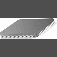
CR16MCS9VJE8 National Semiconductor, CR16MCS9VJE8 Datasheet - Page 67

CR16MCS9VJE8
Manufacturer Part Number
CR16MCS9VJE8
Description
16-Bit Microcontroller IC
Manufacturer
National Semiconductor
Datasheet
1.CR16MCS9VJE8.pdf
(156 pages)
Specifications of CR16MCS9VJE8
Controller Family/series
CR16X
Core Size
16 Bit
Program Memory Size
64K X 8 Flash
Digital Ic Case Style
PQFP
No. Of Pins
80
Mounting Type
Surface Mount
Clock Frequency
25MHz
Lead Free Status / RoHS Status
Contains lead / RoHS non-compliant
Available stocks
Company
Part Number
Manufacturer
Quantity
Price
Company:
Part Number:
CR16MCS9VJE8
Manufacturer:
ON
Quantity:
8 917
Company:
Part Number:
CR16MCS9VJE8-CBB
Manufacturer:
ON
Quantity:
846
Company:
Part Number:
CR16MCS9VJE8-CBC
Manufacturer:
ON
Quantity:
109
Company:
Part Number:
CR16MCS9VJE8-CBD
Manufacturer:
ON
Quantity:
17
Company:
Part Number:
CR16MCS9VJE8-CBE
Manufacturer:
ON
Quantity:
1 950
MSK goes idle again. The MSK idle state can be either high
or low, depending on the MIDL bit.
17.3
In Slave mode, the MSK pin is an input for the shift clock
MSK. MDIDO is placed in TRI-STATE mode when MCS is in-
SLAVE MODE
MSK
Data Out
Data In
Data Out
Data In
MSKn
MSK
Data Out
Data In
MSB
MSB
msb
msb
msb
msb
Figure 28. Alternate Mode, MIDL Bit = 0
Figure 26.
Figure 27.
msb-1
msb-1
msb-1
msb-1
msb-1
msb-1
msb-2 5
Normal Mode, MIDL Bit = 0
Normal Mode, MIDL Bit = 1
msb-2
msb-2
msb-2
msb-2
msb-2
67
active. Data transfer is enabled when MCS is active.
The slave starts driving MDIDO when MCS is activated. The
most significant bit (lower byte in 8-bit mode or upper byte in
16-bit mode) is output onto the MDIDO pin first. After eight or
sixteen clocks (depending on the selected mode), the data
transfer is completed.
Shift Out
Bit 1
Bit 1
Bit 1
Bit 1
Bit 1
Shift Out
Bit 1
Shift Out
Bit 0
(lsb)
Bit 0
(lsb)
Bit 0 (lsb)
Bit 0 (lsb)
Bit 0 (lsb)
Bit 0 (lsb)
End of Transfer
End of Transfer
Sample Point
End of Transfer
Sample Point
Sample Point
www.national.com


