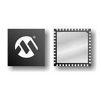
PIC16F724-E/MV Microchip Technology, PIC16F724-E/MV Datasheet - Page 293

PIC16F724-E/MV
Manufacturer Part Number
PIC16F724-E/MV
Description
7KB Flash Program, 1.8V-5.5V, 16MHz Internal Oscillator, 8b ADC, CCP, I2C/SPI, A
Manufacturer
Microchip Technology
Series
PIC® XLP™ 16Fr
Datasheet
1.AC164112.pdf
(302 pages)
Specifications of PIC16F724-E/MV
Processor Series
PIC16F
Core
PIC
Program Memory Type
Flash
Program Memory Size
7 KB
Data Ram Size
192 B
Interface Type
I2C, SPI, AUSART
Number Of Timers
3
Operating Supply Voltage
1.8 V to 5.5 V
Maximum Operating Temperature
+ 125 C
Mounting Style
SMD/SMT
Package / Case
UQFN-40
Development Tools By Supplier
MPLAB IDE Software
Minimum Operating Temperature
- 40 C
Core Processor
PIC
Core Size
8-Bit
Speed
20MHz
Connectivity
I²C, SPI, UART/USART
Peripherals
Brown-out Detect/Reset, POR, PWM, WDT
Number Of I /o
36
Eeprom Size
-
Ram Size
192 x 8
Voltage - Supply (vcc/vdd)
1.8 V ~ 5.5 V
Data Converters
A/D 14x8b
Oscillator Type
Internal
Operating Temperature
-40°C ~ 125°C
Lead Free Status / Rohs Status
Details
INDEX
A
A/D
Absolute Maximum Ratings .............................................. 211
AC Characteristics
ADC .................................................................................... 99
ADCON0 Register....................................................... 24, 104
ADCON1 Register....................................................... 25, 105
Addressable Universal Synchronous Asynchronous
ADRES Register ......................................................... 24, 105
Alternate Pin Function......................................................... 53
Analog-to-Digital Converter. See ADC
ANSELA Register ............................................................... 55
ANSELB Register ............................................................... 64
ANSELD Register ............................................................... 81
ANSELE Register ............................................................... 86
APFCON Register......................................................... 25, 53
Assembler
AUSART ........................................................................... 145
© 2009 Microchip Technology Inc.
Specifications.................................................... 230, 231
Industrial and Extended ............................................ 222
Load Conditions ........................................................ 221
Acquisition Requirements ......................................... 106
Associated registers.................................................. 108
Block Diagram............................................................. 99
Calculating Acquisition Time..................................... 106
Channel Selection..................................................... 100
Configuration............................................................. 100
Configuring Interrupt ................................................. 103
Conversion Clock...................................................... 100
Conversion Procedure .............................................. 103
Internal Sampling Switch (R
Interrupts................................................................... 102
Operation .................................................................. 102
Operation During Sleep ............................................ 102
Port Configuration ..................................................... 100
Reference Voltage (V
Source Impedance.................................................... 106
Special Event Trigger................................................ 102
Receiver Transmitter (AUSART)............................... 145
MPASM Assembler................................................... 208
Associated Registers
Asynchronous Mode ................................................. 147
Baud Rate Generator (BRG)
Synchronous Master Mode ............................... 159, 163
Synchronous Slave Mode
Baud Rate Generator........................................ 156
Associated Registers
Baud Rate Generator (BRG) ............................ 156
Receiver............................................................ 150
Setting up 9-bit Mode with Address Detect....... 152
Transmitter........................................................ 147
Baud Rate Error, Calculating ............................ 156
Baud Rates, Asynchronous Modes .................. 157
Formulas ........................................................... 156
High Baud Rate Select (BRGH Bit) .................. 156
Associated Registers
Reception.......................................................... 161
Transmission .................................................... 159
Associated Registers
Receive..................................................... 153
Transmit.................................................... 149
Receive..................................................... 162
Transmit.................................................... 160
REF
)......................................... 100
SS
) Impedance.............. 106
PIC16F72X/PIC16LF72X
B
BF bit ........................................................................ 175, 187
Block Diagram
Block Diagrams
Brown-out Reset (BOR)...................................................... 37
C
C Compilers
Capacitive Sensing ........................................................... 129
Capacitive Sensing................................................... 129
(CCP) Capture Mode Operation ............................... 137
ADC ............................................................................ 99
ADC Transfer Function............................................. 107
Analog Input Model................................................... 107
AUSART Receive ..................................................... 146
AUSART Transmit .................................................... 145
CCP PWM ................................................................ 141
Clock Source .............................................................. 89
Compare................................................................... 139
Crystal Operation........................................................ 93
External RC Mode ...................................................... 94
Interrupt Logic............................................................. 43
MCLR Circuit .............................................................. 35
On-Chip Reset Circuit................................................. 33
PIC16F722/723/726/PIC16LF722/723/726 ................ 14
PIC16F724/727/PIC16LF724/727 .............................. 15
RA0 Pins..................................................................... 57
RA4 Pin ...................................................................... 58
RA5 Pin ...................................................................... 59
RA6 Pin ...................................................................... 60
RA7 Pin ...................................................................... 60
RB0 Pin ...................................................................... 66
RB3 Pin ...................................................................... 68
RB4, RB2, RB1 Pins................................................... 67
RB5 Pin ...................................................................... 69
RB6 Pin ...................................................................... 70
RB7 Pin ...................................................................... 71
RC0 Pin ...................................................................... 75
RC1 Pin ...................................................................... 75
RC2 Pin ...................................................................... 76
RC3 Pin ...................................................................... 76
RC4 Pin ...................................................................... 77
RC5 Pin ...................................................................... 77
RC6 Pin ...................................................................... 78
RC7 Pin ...................................................................... 78
RD Pins ...................................................................... 82
RE Pins....................................................................... 88
RE3 Pin ...................................................................... 88
Resonator Operation .................................................. 94
SPI Mode.................................................................. 168
SSP (I
Timer1 .............................................. 115, 121, 122, 123
Timer2 ...................................................................... 127
TMR0/WDT Prescaler .............................................. 111
Specifications ........................................................... 228
Timing and Characteristics ....................................... 227
MPLAB C18.............................................................. 208
MPLAB C30.............................................................. 208
Associated registers w/ Capacitive Sensing............. 134
Reception ......................................................... 164
Transmission .................................................... 163
2
C Mode)........................................................ 177
Receive .................................................... 164
Transmit ................................................... 163
DS41341E-page 293


