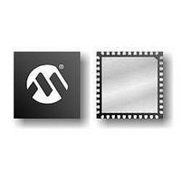
PIC16F724-E/MV Microchip Technology, PIC16F724-E/MV Datasheet - Page 94

PIC16F724-E/MV
Manufacturer Part Number
PIC16F724-E/MV
Description
7KB Flash Program, 1.8V-5.5V, 16MHz Internal Oscillator, 8b ADC, CCP, I2C/SPI, A
Manufacturer
Microchip Technology
Series
PIC® XLP™ 16Fr
Datasheet
1.AC164112.pdf
(302 pages)
Specifications of PIC16F724-E/MV
Processor Series
PIC16F
Core
PIC
Program Memory Type
Flash
Program Memory Size
7 KB
Data Ram Size
192 B
Interface Type
I2C, SPI, AUSART
Number Of Timers
3
Operating Supply Voltage
1.8 V to 5.5 V
Maximum Operating Temperature
+ 125 C
Mounting Style
SMD/SMT
Package / Case
UQFN-40
Development Tools By Supplier
MPLAB IDE Software
Minimum Operating Temperature
- 40 C
Core Processor
PIC
Core Size
8-Bit
Speed
20MHz
Connectivity
I²C, SPI, UART/USART
Peripherals
Brown-out Detect/Reset, POR, PWM, WDT
Number Of I /o
36
Eeprom Size
-
Ram Size
192 x 8
Voltage - Supply (vcc/vdd)
1.8 V ~ 5.5 V
Data Converters
A/D 14x8b
Oscillator Type
Internal
Operating Temperature
-40°C ~ 125°C
Lead Free Status / Rohs Status
Details
- Current page: 94 of 302
- Download datasheet (5Mb)
PIC16F72X/PIC16LF72X
FIGURE 7-4:
7.6.4
The external Resistor-Capacitor (RC) modes support
the use of an external RC circuit. This allows the
designer maximum flexibility in frequency choice while
keeping costs to a minimum when clock accuracy is not
required. There are two modes: RC and RCIO.
In RC mode, the RC circuit connects to OSC1.
OSC2/CLKOUT outputs the RC oscillator frequency
divided by 4. This signal may be used to provide a clock
for external circuitry, synchronization, calibration, test
or other application requirements. Figure 7-5 shows
the external RC mode connections.
TABLE 7-1:
DS41341E-page 94
CONFIG1
OSCCON
OSCTUNE
Legend:
Note 1:
Note 1: A series resistor (R
Name
C1
C2 Ceramic
2: The value of R
3: An additional parallel feedback resistor (R
(1)
Resonator
ceramic resonators with low drive level.
selected.
may be required for proper ceramic resonator
operation.
x = unknown, u = unchanged, – = unimplemented locations read as ‘0’. Shaded cells are not used by oscillators.
See Configuration Word 1 (Register 8-1) for operation of all bits.
EXTERNAL RC MODES
Bit 7
—
—
—
SUMMARY OF REGISTERS ASSOCIATED WITH CLOCK SOURCES
R
P
R
(3)
S (1)
CERAMIC RESONATOR
OPERATION
(XT OR HS MODE)
F
varies with the Oscillator mode
Bit 6
CP
OSC1/CLKIN
OSC2/CLKOUT
—
—
S
R
) may be required for
F
(2)
MCLRE
IRCF1
TUN5
PIC
Bit 5
®
MCU
To Internal
Logic
Sleep
PWRTE
IRCF0
TUN4
Bit 4
P
)
WDTE
TUN3
Bit 3
ICSL
FOSC2
FIGURE 7-5:
In RCIO mode, the RC circuit is connected to OSC1.
OSC2 becomes an additional general purpose I/O pin.
The RC oscillator frequency is a function of the supply
voltage, the resistor (R
and the operating temperature. Other factors affecting
the oscillator frequency are:
• threshold voltage variation
• component tolerances
• packaging variations in capacitance
The user also needs to take into account variation due
to tolerance of external RC components used.
TUN2
ICSS
Bit 2
R
C
Note 1:
V
Recommended values: 10 kΩ ≤ R
EXT
EXT
SS
V
F
I/O
OSC
DD
(2)
2:
FOSC1
TUN1
Bit 1
/4 or
—
Alternate pin functions are described in
Section 6.1 “Alternate Pin Function”.
Output depends upon RC or RCIO clock mode.
FOSC0
TUN0
Bit 0
OSC1/CLKIN
OSC2/CLKOUT
—
EXT
EXTERNAL RC MODES
© 2009 Microchip Technology Inc.
3 kΩ ≤ R
C
EXT
) and capacitor (C
--10 qq--
--00 0000
POR, BOR
> 20 pF, 2-5V
Value on
PIC
EXT
—
EXT
(1)
®
≤ 100 kΩ, 3-5V
MCU
≤ 100 kΩ, <3V
--10 qq--
--uu uuuu
EXT
Resets
Value on
all other
Internal
Clock
—
) values
(1)
Related parts for PIC16F724-E/MV
Image
Part Number
Description
Manufacturer
Datasheet
Request
R

Part Number:
Description:
IC PIC MCU FLASH 4KX14 44-QFN
Manufacturer:
Microchip Technology
Datasheet:

Part Number:
Description:
IC PIC MCU FLASH 4KX14 44TQFP
Manufacturer:
Microchip Technology
Datasheet:

Part Number:
Description:
IC PIC MCU FLASH 4KX14 40-DIP
Manufacturer:
Microchip Technology
Datasheet:

Part Number:
Description:
7KB Flash Program, 1.8V-5.5V, 16MHz Internal Oscillator, 8b ADC, CCP, I2C/SPI, A
Manufacturer:
Microchip Technology
Datasheet:

Part Number:
Description:
7KB Flash Program, 1.8V-5.5V, 16MHz Internal Oscillator, 8b ADC, CCP, I2C/SPI, A
Manufacturer:
Microchip Technology
Datasheet:

Part Number:
Description:
7KB Flash Program, 1.8V-5.5V, 16MHz Internal Oscillator, 8b ADC, CCP, I2C/SPI, A
Manufacturer:
Microchip Technology
Datasheet:

Part Number:
Description:
7KB Flash Program, 1.8V-5.5V, 16MHz Internal Oscillator, 8b ADC, CCP, I2C/SPI, A
Manufacturer:
Microchip Technology

Part Number:
Description:
IC PIC MCU FLASH 2KX14 28-QFN
Manufacturer:
Microchip Technology
Datasheet:

Part Number:
Description:
IC PIC MCU FLASH 2KX14 28-SOIC
Manufacturer:
Microchip Technology
Datasheet:

Part Number:
Description:
IC PIC MCU FLASH 2KX14 28DIP
Manufacturer:
Microchip Technology
Datasheet:

Part Number:
Description:
IC PIC MCU FLASH 2KX14 28-SOIC
Manufacturer:
Microchip Technology
Datasheet:

Part Number:
Description:
IC PIC MCU FLASH 2KX14 28QFN
Manufacturer:
Microchip Technology

Part Number:
Description:
IC PIC MCU FLASH 2KX14 28SSOP
Manufacturer:
Microchip Technology

Part Number:
Description:
IC PIC MCU FLASH 2KX14 8-SSOP
Manufacturer:
Microchip Technology
Datasheet:

Part Number:
Description:
IC PIC MCU FLASH 2KX14 28-SSOP
Manufacturer:
Microchip Technology
Datasheet:


