AD9957BSVZ Analog Devices Inc, AD9957BSVZ Datasheet - Page 22
AD9957BSVZ
Manufacturer Part Number
AD9957BSVZ
Description
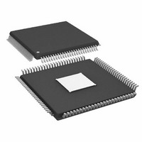
IC DDS 1GSPS 14BIT IQ 100TQFP
Manufacturer
Analog Devices Inc
Datasheet
1.AD9957BSVZ-REEL.pdf
(64 pages)
Specifications of AD9957BSVZ
Resolution (bits)
14 b
Master Fclk
1GHz
Tuning Word Width (bits)
32 b
Voltage - Supply
1.8V, 3.3V
Operating Temperature
-40°C ~ 85°C
Mounting Type
Surface Mount
Package / Case
100-TQFP Exposed Pad, 100-eTQFP, 100-HTQFP, 100-VQFP
Frequency Range
60MHz To 1GHz
Rf Type
Quadrature
Supply Voltage Range
1.71V To 1.89V, 3.135V To 3.465
Rf Ic Case Style
TQFP
No. Of Pins
100
Operating Temperature Range
-40°C To +85°C
Operating Temperature (max)
85C
Operating Temperature (min)
-40C
Pin Count
100
Mounting
Surface Mount
Case Height
1mm
Screening Level
Industrial
Lead Free Status / RoHS Status
Lead free / RoHS Compliant
For Use With
AD9957/PCBZ - BOARD EVAL AD9957 QUADRATURE MOD
Lead Free Status / Rohs Status
Compliant
Available stocks
Company
Part Number
Manufacturer
Quantity
Price
Company:

Part Number:
AD9957BSVZ
Manufacturer:
AD
Quantity:
1 200
Company:
Part Number:
AD9957BSVZ
Manufacturer:
Analog Devices Inc
Quantity:
10 000
Part Number:
AD9957BSVZ
Manufacturer:
ADI/亚德诺
Quantity:
20 000
Company:
Part Number:
AD9957BSVZ-REEL
Manufacturer:
Analog Devices Inc
Quantity:
10 000
Part Number:
AD9957BSVZ-REEL
Manufacturer:
ADI/亚德诺
Quantity:
20 000


AD9957
INPUT DATA ASSEMBLER
The input to the AD9957 is an 18-bit parallel data port in
QDUC mode or interpolating DAC mode. In BFI mode, it
operates as a dual serial data port.
In QDUC mode, it is assumed that two consecutive 18-bit
words represent the real (I) and imaginary (Q) parts of a
complex number of the form, I + jQ. The 18-bit words are
supplied to the input of the AD9957 at a rate of
where:
f
sample rate of the DAC.
R (for all of the PDCLK equations in this section) is the
interpolation factor of the programmable interpolation filter.
SYSCLK
f
(for all of the PDCLK equations in this section) is the
PDCLK
TxENABLE
TxENABLE
D<17:0>
D<17:0>
PDCLK
PDCLK
TxENABLE
Q DATA
=
PDCLK
I DATA
f
SYSCLK
2
R
Q
I
0
0
for QDUC mode
Q
I
1
1
t
t
DS
DS
t
t
DS
DS
Q
I
2
2
Figure 31. 18-Bit Parallel Port Timing Diagram—Quadrature Modulation Mode
I
I
0
0
Figure 30. 18-Bit Parallel Port Timing Diagram—Interpolating DAC Mode
t
t
DH
DH
Q
I
3
3
Figure 32. Dual Serial I/Q Bit Stream Timing Diagram, BFI Mode
Q
I
4
4
Q
I
1
Q
0
I
5
5
Q
I
6
6
Rev. B | Page 22 of 64
Q
I
I
I
7
2
1
7
Q
I
8
8
When the PDCLK rate control bit is active in QDUC mode,
however, the frequency of PDCLK becomes
In the interpolating DAC mode, the rate of PDCLK is the same
as QDUC mode with the PDCLK rate control bit active, that is,
In BFI mode, the 18-bit parallel input converts to a dual serial
input that is, one pin is assigned as the serial input for the I-words
and one pin is assigned as the serial input for the Q-words. The
other 16 pins are not used. Furthermore, each I- and Q-word
has a 16-bit resolution. f
streams and is given by
Q
I
9
9
Q
I
3
1
f
f
f
Q
PDCLK
PDCLK
PDCLK
I
10
10
Q
=
=
=
I
11
11
f
f
f
SYSCLK
SYSCLK
SYSCLK
4
4
R
Q
R
R
I
12
12
with PDCLK rate control active
for interpolating DAC mode
for BFI mode
Q
PDCLK
I
13
13
I
is the bit rate of the I- and Q-data
K – 1
Q
I
I
14
N
14
Q
I
15
15
t
t
DH
DH
Q
I
16n – 1
16n – 1
Q
I
K
N
Related parts for AD9957BSVZ
Image
Part Number
Description
Manufacturer
Datasheet
Request
R

Part Number:
Description:
D/A Converter Evaluation Board
Manufacturer:
Analog Devices Inc
Datasheet:


Part Number:
Description:
±1.7g Dual-Axis IMEMS Accelerometer Evaluation Board
Manufacturer:
Analog Devices Inc
Datasheet:

Part Number:
Description:
Inertial Sensor Evaluation System
Manufacturer:
Analog Devices Inc
Datasheet:
Part Number:
Description:
Manufacturer:
Analog Devices Inc
Datasheet:
Part Number:
Description:
Manufacturer:
Analog Devices Inc
Datasheet:
Part Number:
Description:
Manufacturer:
Analog Devices Inc
Datasheet:
Part Number:
Description:
Manufacturer:
Analog Devices Inc
Datasheet:
Part Number:
Description:
Manufacturer:
Analog Devices Inc
Datasheet:
Part Number:
Description:
Manufacturer:
Analog Devices Inc
Datasheet:
Part Number:
Description:
Manufacturer:
Analog Devices Inc
Datasheet:
Part Number:
Description:
Manufacturer:
Analog Devices Inc
Datasheet:
Part Number:
Description:
Manufacturer:
Analog Devices Inc
Datasheet: