AD9957BSVZ Analog Devices Inc, AD9957BSVZ Datasheet - Page 55
AD9957BSVZ
Manufacturer Part Number
AD9957BSVZ
Description
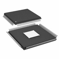
IC DDS 1GSPS 14BIT IQ 100TQFP
Manufacturer
Analog Devices Inc
Datasheet
1.AD9957BSVZ-REEL.pdf
(64 pages)
Specifications of AD9957BSVZ
Resolution (bits)
14 b
Master Fclk
1GHz
Tuning Word Width (bits)
32 b
Voltage - Supply
1.8V, 3.3V
Operating Temperature
-40°C ~ 85°C
Mounting Type
Surface Mount
Package / Case
100-TQFP Exposed Pad, 100-eTQFP, 100-HTQFP, 100-VQFP
Frequency Range
60MHz To 1GHz
Rf Type
Quadrature
Supply Voltage Range
1.71V To 1.89V, 3.135V To 3.465
Rf Ic Case Style
TQFP
No. Of Pins
100
Operating Temperature Range
-40°C To +85°C
Operating Temperature (max)
85C
Operating Temperature (min)
-40C
Pin Count
100
Mounting
Surface Mount
Case Height
1mm
Screening Level
Industrial
Lead Free Status / RoHS Status
Lead free / RoHS Compliant
For Use With
AD9957/PCBZ - BOARD EVAL AD9957 QUADRATURE MOD
Lead Free Status / Rohs Status
Compliant
Available stocks
Company
Part Number
Manufacturer
Quantity
Price
Company:

Part Number:
AD9957BSVZ
Manufacturer:
AD
Quantity:
1 200
Company:
Part Number:
AD9957BSVZ
Manufacturer:
Analog Devices Inc
Quantity:
10 000
Part Number:
AD9957BSVZ
Manufacturer:
ADI/亚德诺
Quantity:
20 000
Company:
Part Number:
AD9957BSVZ-REEL
Manufacturer:
Analog Devices Inc
Quantity:
10 000
Part Number:
AD9957BSVZ-REEL
Manufacturer:
ADI/亚德诺
Quantity:
20 000


REGISTER BIT DESCRIPTIONS
The serial I/O port registers span an address range of 0 to 25
(0x00 to 0x19 in hexadecimal notation). This represents a total
of 26 registers. However, six of these registers are unused, yielding
a total of 20 available registers. The unused registers are 7, 8, 11
to 13, and 23 (0x07 to 0x08, 0x0B to 0x0D, and 0x17).
The number of bytes assigned to the registers varies. That is, the
registers are not of uniform depth; each contains the number
of bytes necessary for its particular function. Additionally, the
registers are assigned names according to their functionality.
In some cases, a register is given a mnemonic descriptor. For
example, the register at Serial Address 0x00 is named Control
Function Register 1 and is assigned the mnemonic CFR1.
Control Function Register 1 (CFR1)
Address 0x00, four bytes are assigned to this register.
Table 18. Bit Descriptions for CFR1 Register
Bit (s)
31
30:29
28
27:26
25:24
23
22
21
20:17
16
15:14
13
12
11
10
Mnemonic
RAM Enable
Open
RAM Playback
Destination
Open
Operating Mode
Manual OSK
External Control
Inverse Sinc Filter
Enable
Clear CCI
Open
Select DDS Sine
Output
Open
Autoclear Phase
Accumulator
Open
Clear Phase
Accumulator
Load ARR @ I/O
Update
Description
0: disables RAM playback functionality (default).
1: enables RAM playback functionality.
Ineffective unless CFR1<31> = 1.
00: quadrature modulation mode (default).
01: single tone mode.
1x: interpolating DAC mode.
Ineffective unless CFR1<9:8> = 10b.
0: inverse sinc filter bypassed (default).
1: inverse sinc filter active.
This bit is automatically cleared by the serial I/O port controller. This operation requires several internal clock
cycles to complete, during which time the data supplied to the CCI input by the baseband signal chain is
ignored. The inputs are forced to all zeros to flush the CCI data path, after which the CCI accumulators are reset.
Ineffective unless CFR1<25:24> = 01b.
0: normal operation of the DDS phase accumulator (default).
1: synchronously resets the DDS phase accumulator any time I/O_UPDATE is asserted or a profile
change occurs.
0: normal operation of the DDS phase accumulator (default).
1: asynchronous, static reset of the DDS phase accumulator.
0: normal operation of the OSK amplitude ramp rate timer (default).
1: OSK amplitude ramp rate timer reloaded any time I/O_UPDATE is asserted or a profile change occurs.
0: RAM playback data routed to baseband scaling multipliers (default).
1: RAM playback data routed to baseband I/Q data path.
0: OSK pin inoperative (default).
1: OSK pin enabled for manual OSK control (see the Output Shift Keying (OSK) section).
0: normal operation of the CCI filter (default).
1: initiates an asynchronous reset of the accumulators in the CCI filter.
0: cosine output of the DDS is selected (default).
1: sine output of the DDS is selected.
Rev. B | Page 55 of 64
The following section provides a detailed description of each bit
in the AD9957 register map. For cases in which a group of bits
serve a specific function, the entire group is considered as a
binary word and described in aggregate.
This section is organized in sequential order of the serial
addresses of the registers. Following each subheading are the
individual bit descriptions for that particular register. The
location of the bit(s) in the register are indicated by <A> or
<A:B>, where A and B are bit numbers. The notation, <A:B>,
specifies a range of bits from most significant to least significant
bit position. For example, <5:2> means bit positions 5 down to
2, inclusive, with Bit 0 identifying the LSB of the register.
Unless otherwise stated, programmed bits are not transferred to
their internal destinations until the assertion of an I/O update or
profile change.
AD9957
Related parts for AD9957BSVZ
Image
Part Number
Description
Manufacturer
Datasheet
Request
R

Part Number:
Description:
D/A Converter Evaluation Board
Manufacturer:
Analog Devices Inc
Datasheet:


Part Number:
Description:
±1.7g Dual-Axis IMEMS Accelerometer Evaluation Board
Manufacturer:
Analog Devices Inc
Datasheet:

Part Number:
Description:
Inertial Sensor Evaluation System
Manufacturer:
Analog Devices Inc
Datasheet:
Part Number:
Description:
Manufacturer:
Analog Devices Inc
Datasheet:
Part Number:
Description:
Manufacturer:
Analog Devices Inc
Datasheet:
Part Number:
Description:
Manufacturer:
Analog Devices Inc
Datasheet:
Part Number:
Description:
Manufacturer:
Analog Devices Inc
Datasheet:
Part Number:
Description:
Manufacturer:
Analog Devices Inc
Datasheet:
Part Number:
Description:
Manufacturer:
Analog Devices Inc
Datasheet:
Part Number:
Description:
Manufacturer:
Analog Devices Inc
Datasheet:
Part Number:
Description:
Manufacturer:
Analog Devices Inc
Datasheet:
Part Number:
Description:
Manufacturer:
Analog Devices Inc
Datasheet: