AD9957BSVZ Analog Devices Inc, AD9957BSVZ Datasheet - Page 32
AD9957BSVZ
Manufacturer Part Number
AD9957BSVZ
Description
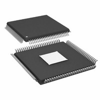
IC DDS 1GSPS 14BIT IQ 100TQFP
Manufacturer
Analog Devices Inc
Datasheet
1.AD9957BSVZ-REEL.pdf
(64 pages)
Specifications of AD9957BSVZ
Resolution (bits)
14 b
Master Fclk
1GHz
Tuning Word Width (bits)
32 b
Voltage - Supply
1.8V, 3.3V
Operating Temperature
-40°C ~ 85°C
Mounting Type
Surface Mount
Package / Case
100-TQFP Exposed Pad, 100-eTQFP, 100-HTQFP, 100-VQFP
Frequency Range
60MHz To 1GHz
Rf Type
Quadrature
Supply Voltage Range
1.71V To 1.89V, 3.135V To 3.465
Rf Ic Case Style
TQFP
No. Of Pins
100
Operating Temperature Range
-40°C To +85°C
Operating Temperature (max)
85C
Operating Temperature (min)
-40C
Pin Count
100
Mounting
Surface Mount
Case Height
1mm
Screening Level
Industrial
Lead Free Status / RoHS Status
Lead free / RoHS Compliant
For Use With
AD9957/PCBZ - BOARD EVAL AD9957 QUADRATURE MOD
Lead Free Status / Rohs Status
Compliant
Available stocks
Company
Part Number
Manufacturer
Quantity
Price
Company:

Part Number:
AD9957BSVZ
Manufacturer:
AD
Quantity:
1 200
Company:
Part Number:
AD9957BSVZ
Manufacturer:
Analog Devices Inc
Quantity:
10 000
Part Number:
AD9957BSVZ
Manufacturer:
ADI/亚德诺
Quantity:
20 000
Company:
Part Number:
AD9957BSVZ-REEL
Manufacturer:
Analog Devices Inc
Quantity:
10 000
Part Number:
AD9957BSVZ-REEL
Manufacturer:
ADI/亚德诺
Quantity:
20 000


AD9957
RAM Continuous Bidirectional Ramp Mode
In continuous bidirectional ramp mode, upon assertion of an
I/O update or a state change on the RT pin, the RAM begins
playback operation using the parameters programmed into the
selected RAM segment register. Data is extracted from RAM
over the specified address range contained in the start address
and end address. The data is delivered at the appropriate rate
and to the destination as specified by the RAM playback
destination bit.
The playback rate is governed by the timer internal to the RAM
state machine and its period (Δt) is determined by the state of
the RAM playback destination bit as detailed in the RAM
Playback Operation section.
After initialization, the internal state machine begins extracting
data from the RAM at the start address of the active RAM segment
register and increments the address counter until it reaches the
end address, at which point the state machine reverses the direc-
tion of the address counter and begins decrementing through
the address range. Whenever one of the terminal addresses is
reached, the state machine reverses the address counter; the
process continues indefinitely.
I/O_UPDATE OR
RT TRANSITION
ADDRESS
RAM
M DDS CLOCK CYCLES
1 PDCLK CYCLE
1
OR
Figure 45. Continuous Bidirectional Ramp Timing Diagram
END ADDRESS
START ADDRESS
1
Rev. B | Page 32 of 64
Δ
t
2
Note that a change in state of the RT pin aborts the current
waveform and the newly selected RAM segment register is used
to initiate a new waveform.
A graphic representation of the continuous bidirectional ramp
mode is shown in Figure 45. The circled numbers in Figure 45
indicate specific events, explained as follows:
Event 1—an I/O update or state change on the RT pin has
activated the RAM continuous bidirectional ramp mode. The
state machine initializes to the start address of the active RAM
segment register. The state machine begins incrementing
through the specified address range.
Event 2—the state machine reaches the end address of the active
RAM segment register.
Event 3—the state machine reaches the start address of the
active RAM segment register.
The continuous bidirectional ramp continues indefinitely until
the next I/O update or state change on the RT pin.
Δ
t
3
Related parts for AD9957BSVZ
Image
Part Number
Description
Manufacturer
Datasheet
Request
R

Part Number:
Description:
D/A Converter Evaluation Board
Manufacturer:
Analog Devices Inc
Datasheet:


Part Number:
Description:
±1.7g Dual-Axis IMEMS Accelerometer Evaluation Board
Manufacturer:
Analog Devices Inc
Datasheet:

Part Number:
Description:
Inertial Sensor Evaluation System
Manufacturer:
Analog Devices Inc
Datasheet:
Part Number:
Description:
Manufacturer:
Analog Devices Inc
Datasheet:
Part Number:
Description:
Manufacturer:
Analog Devices Inc
Datasheet:
Part Number:
Description:
Manufacturer:
Analog Devices Inc
Datasheet:
Part Number:
Description:
Manufacturer:
Analog Devices Inc
Datasheet:
Part Number:
Description:
Manufacturer:
Analog Devices Inc
Datasheet:
Part Number:
Description:
Manufacturer:
Analog Devices Inc
Datasheet:
Part Number:
Description:
Manufacturer:
Analog Devices Inc
Datasheet:
Part Number:
Description:
Manufacturer:
Analog Devices Inc
Datasheet:
Part Number:
Description:
Manufacturer:
Analog Devices Inc
Datasheet: