AD9957BSVZ Analog Devices Inc, AD9957BSVZ Datasheet - Page 59
AD9957BSVZ
Manufacturer Part Number
AD9957BSVZ
Description
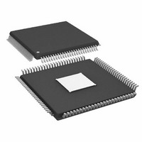
IC DDS 1GSPS 14BIT IQ 100TQFP
Manufacturer
Analog Devices Inc
Datasheet
1.AD9957BSVZ-REEL.pdf
(64 pages)
Specifications of AD9957BSVZ
Resolution (bits)
14 b
Master Fclk
1GHz
Tuning Word Width (bits)
32 b
Voltage - Supply
1.8V, 3.3V
Operating Temperature
-40°C ~ 85°C
Mounting Type
Surface Mount
Package / Case
100-TQFP Exposed Pad, 100-eTQFP, 100-HTQFP, 100-VQFP
Frequency Range
60MHz To 1GHz
Rf Type
Quadrature
Supply Voltage Range
1.71V To 1.89V, 3.135V To 3.465
Rf Ic Case Style
TQFP
No. Of Pins
100
Operating Temperature Range
-40°C To +85°C
Operating Temperature (max)
85C
Operating Temperature (min)
-40C
Pin Count
100
Mounting
Surface Mount
Case Height
1mm
Screening Level
Industrial
Lead Free Status / RoHS Status
Lead free / RoHS Compliant
For Use With
AD9957/PCBZ - BOARD EVAL AD9957 QUADRATURE MOD
Lead Free Status / Rohs Status
Compliant
Available stocks
Company
Part Number
Manufacturer
Quantity
Price
Company:

Part Number:
AD9957BSVZ
Manufacturer:
AD
Quantity:
1 200
Company:
Part Number:
AD9957BSVZ
Manufacturer:
Analog Devices Inc
Quantity:
10 000
Part Number:
AD9957BSVZ
Manufacturer:
ADI/亚德诺
Quantity:
20 000
Company:
Part Number:
AD9957BSVZ-REEL
Manufacturer:
Analog Devices Inc
Quantity:
10 000
Part Number:
AD9957BSVZ-REEL
Manufacturer:
ADI/亚德诺
Quantity:
20 000


RAM Segment Register 1
Address 0x06, six bytes are assigned to this register. This register is only active if CFR1<31> = 1 and there is a Logic 1 to Logic 0 transition
on the RT pin.
Table 24. Bit Descriptions for RAM Segment Register 1
Bit(s)
47:32
31:22
21:16
15:6
5:3
2:0
Amplitude Scale Factor (ASF) Register
Address 0x09, four bytes are assigned to this register. This register is only active if CFR1<9> = 1.
Table 25. Bit Descriptions for ASF Register
Bit(s)
31:16
15:2
1:0
Multichip Sync Register
Address 0x0A, four bytes are assigned to this register.
Table 26. Bit Descriptions for the Multichip Sync Register
Bit(s)
31:28
27
26
25
24
23:18
17:16
15:11
10:8
7:3
2:0
Mnemonic
Sync Validation Delay
Sync Receiver Enable
Sync Generator Enable
Sync Generator Polarity
Open
Sync State Preset Value
Open
Sync Generator Delay
Open
Sync Receiver Delay
Open
Mnemonic
RAM Address Step
Rate 1
RAM End Address 1
Open
RAM Start Address 1
Open
RAM Playback Mode 1
Mnemonic
Amplitude Ramp Rate
Amplitude Scale Factor
Amplitude Step Size
Description
This 16-bit number controls the rate at which the RAM state machine steps through the specified RAM
address range.
This 10-bit number identifies the ending address for the RAM state machine.
This 10-bit number identifies the starting address for the RAM state machine.
This 3-bit number identifies the playback mode for the RAM state machine (see Table 5).
Description
Default is 0000b. This 4-bit number sets the timing skew (in ~150 ps increments) between SYSCLK and
the delayed sync-in signal for the synchronization validation block in the synchronization receiver.
0: synchronization clock receiver disabled (default).
1: synchronization clock receiver enabled.
0: synchronization clock generator disabled (default).
1: synchronization clock generator enabled.
0: synchronization clock generator coincident with the rising edge of the system clock (default).
1: synchronization clock generator coincident with the falling edge of the system clock.
Default is 000000b. This 6-bit number is the state that the internal clock generator assumes when it
receives a sync pulse.
Default is 00000b. This 5-bit number sets the output delay (in ~150 ps increments) of the
synchronization generator.
Default is 00000b. This 5-bit number sets the delay input delay (in ~150 ps increments) of the
synchronization receiver.
Description
Ineffective unless CFR1<8> = 1. This 16-bit number controls the rate at which the OSK controller
updates amplitude changes to the DDS.
If CFR1<8> = 0 and CFR1<23> = 0, then this 14-bit number is the amplitude scale factor for the DDS.
If CFR1<8> = 0 and CFR1<23> = 1, then this 14-bit number is the amplitude scale factor for the DDS
when the OSK pin is Logic 1.
If CFR1<8> = 1, then this 14-bit number sets a ceiling on the maximum allowable amplitude scale factor
for the DDS.
Ineffective unless CFR1<8> = 1. This 2-bit number controls the step size for amplitude changes to the
DDS (see Table 9).
Rev. B | Page 59 of 64
AD9957
Related parts for AD9957BSVZ
Image
Part Number
Description
Manufacturer
Datasheet
Request
R

Part Number:
Description:
D/A Converter Evaluation Board
Manufacturer:
Analog Devices Inc
Datasheet:


Part Number:
Description:
±1.7g Dual-Axis IMEMS Accelerometer Evaluation Board
Manufacturer:
Analog Devices Inc
Datasheet:

Part Number:
Description:
Inertial Sensor Evaluation System
Manufacturer:
Analog Devices Inc
Datasheet:
Part Number:
Description:
Manufacturer:
Analog Devices Inc
Datasheet:
Part Number:
Description:
Manufacturer:
Analog Devices Inc
Datasheet:
Part Number:
Description:
Manufacturer:
Analog Devices Inc
Datasheet:
Part Number:
Description:
Manufacturer:
Analog Devices Inc
Datasheet:
Part Number:
Description:
Manufacturer:
Analog Devices Inc
Datasheet:
Part Number:
Description:
Manufacturer:
Analog Devices Inc
Datasheet:
Part Number:
Description:
Manufacturer:
Analog Devices Inc
Datasheet:
Part Number:
Description:
Manufacturer:
Analog Devices Inc
Datasheet:
Part Number:
Description:
Manufacturer:
Analog Devices Inc
Datasheet: