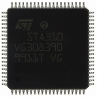
STA310 STMicroelectronics, STA310 Datasheet - Page 19

STA310
Manufacturer Part Number
STA310
Description
IC AUDIO DECODER 6+2CH 80-TQFP
Manufacturer
STMicroelectronics
Type
Audio Decoderr
Datasheet
1.STA310.pdf
(90 pages)
Specifications of STA310
Applications
HDTV, Players, Receivers, Set-Top Boxes
Voltage - Supply, Analog
2.5V
Voltage - Supply, Digital
2.5V
Mounting Type
Surface Mount
Package / Case
80-TQFP, 80-VQFP
Audio Codec Type
MP3 Decoder
No. Of Dacs
3
No. Of Input Channels
2
No. Of Output Channels
6
Adc / Dac Resolution
32bit
Sampling Rate
192kHz
Interface Type
I2C, Serial, Parallel
Rohs Compliant
Yes
Lead Free Status / RoHS Status
Lead free / RoHS Compliant
Other names
497-8856
STA310
STA310
Available stocks
Company
Part Number
Manufacturer
Quantity
Price
Part Number:
STA310
Manufacturer:
ST
Quantity:
20 000
These modes refer to different implementation of the dialog normalization and dynamic range control features.
The mode is selected by programming the register COMP_MOD to the appropriate value.
Line Mode
In Line Mode (COMP_MOD = 2), the dialog normalization is always enabled. It is done by the decoder itself and
the dialog is reproduced at a constant level.
The dynamic range control variable encoded in the bitstream is used and can be scaled by the two scaling reg-
isters HDR (for high-level cut compression) and LDR (for low-level boost compression). In case of 2/0 downmix,
the high-level cut compression is not scalable.
RF Mode
In RF Mode (COMP_MOD=3), the dialog normalization is always performed by the decoder. The dialog is re-
produced at a constant level.
The dynamic range control and heavy compression variables encoded in the bitstream are used, but the com-
pression scaling is not allowed. This means that the HDR and LDR registers can not be used in this mode. A
+11dB gain shift is applied on the output channels.
Custom A Mode
In Custom A mode (COMP_MOD=0), the dialog normalization is not performed by the decoder and must be
done by another circuit externally.
The dynamic range control variable encoded in the bitstream is used and can be scaled by the two scaling reg-
isters HDR (for high-level cut compression) and LDR (for low-level boost compression).
Custom D Mode
In Custom D mode (COMP_MOD=1), the dialog normalization is performed by the decoder. The dynamic range
control variable encoded in the bitstream is used and can be scaled by the two scaling registers HDR (for high-
level cut compression) and LDR (for low-level boost compression).
4.6.1.2 Karaoke mode
The AC-3 decoder is karaoke aware and capable.
A karaoke bitstream can be composed of 5 channels: L for Left, R for Right, M for guide Melody, V1 for vocal
track 1 and V2 for Vocal track 2.
The karaoke decoder is activated by the use of KARAMODE register, which specifies the downmix for the dif-
ferent modes. This register replaces DOWNMIX register. It is however possible to consider the incoming
karaoke channels as any other multichannel stream and output it with a downmix specified in DOWNMIX reg-
ister. For details, refer to the Digital Audio Compression AC-3 ATSC standard, annex C.
- Custom A (also named custom 0 in Dolby specifications),
- Custom D (also named custom 1 in Dolby specifications),
- Line mode,
- RF mode.
- When in karaoke aware mode, the channels L,R and M are reproduced, and the channels V1 and V2
- When in karaoke capable mode, it is possible to choose to reproduce one, two or none of the two
are reproduced at a level fixed by the bitstream.
incoming vocal tracks, V1 and V2.
STA310
19/90


