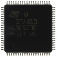
STA310 STMicroelectronics, STA310 Datasheet - Page 39

STA310
Manufacturer Part Number
STA310
Description
IC AUDIO DECODER 6+2CH 80-TQFP
Manufacturer
STMicroelectronics
Type
Audio Decoderr
Datasheet
1.STA310.pdf
(90 pages)
Specifications of STA310
Applications
HDTV, Players, Receivers, Set-Top Boxes
Voltage - Supply, Analog
2.5V
Voltage - Supply, Digital
2.5V
Mounting Type
Surface Mount
Package / Case
80-TQFP, 80-VQFP
Audio Codec Type
MP3 Decoder
No. Of Dacs
3
No. Of Input Channels
2
No. Of Output Channels
6
Adc / Dac Resolution
32bit
Sampling Rate
192kHz
Interface Type
I2C, Serial, Parallel
Rohs Compliant
Yes
Lead Free Status / RoHS Status
Lead free / RoHS Compliant
Other names
497-8856
STA310
STA310
Available stocks
Company
Part Number
Manufacturer
Quantity
Price
Part Number:
STA310
Manufacturer:
ST
Quantity:
20 000
Software Reset: NA
Hardware Reset: NA
Description:
This version register is read only and is used to iden-
tify the audio hardware version. The version register
holds a number which refers to the cut number. The
version numbers are defined as below:
9.4 SETUP & INPUT REGISTERS
The STA310 can get receive an input bitstream either
from the I2s input or ffrom the Spdif input, the selec-
tion and the configuration is done through 2 registers
SIN_SETUP @ 12 and CAN_SETUP @ 13.
SIN SETUP
Input data setup
Address: 0x0C
Type: R/W
Software Reset: NC
Hardware Reset: 0
Description:
This register is used to configure the input data inter-
face. The register must be setup before sending data
to the IC. The mapping of the register isescribed be-
low. Remember that the data must be sent to the de-
vice MSB first.
The configuration of the 3 possible interfaces is
7
- STA310 cut 1.0, version number is : 0x10
- STA310 cut 2.0, version number is : 0x10
- SPDIF data frpm SPDIF when set to 1, data
- POL Polarity of the REQ signal. When set,
- IMODE[1...0] Input mode. Indicates which
from main I
the REQ pin is active low: data must be input
when REQ is low. When reset, the REQ pin is
active high and data must be input when REQ
is high.
data input interface is used.
6
5
2
S input.
4
SPDIF
3
POL
2
IMODE [1...0]
1
0
shown below:
When the IC is configured in mode 1 or 3, the
CAN_SETUP register is used to configure the IC with
repect to the data format.
CAN_SETUP
A/D converter setup
Address : 0x0D
Type: R/W
Software Reset: NC
Hardware Reset: 0
Description:
CAN_SETUP is used to configure the data serial in-
terface. The register is only taken into account when
the register sin_setup [1...0] = 3.
Also see SIN_SETUP register./
When the IC is configured with the S/PDIF input, reg-
ister CAN_SETUP must be set to 2
DATAIN
Data input
IMODE[1:0]
- S16 When set, the slot count is 16. When re-
- SAM When set data is sampled on the falling
- FIR When set the first channel (Left) is input
- PAD When set, data Lrclkin is delayed by one
7
7
set, the slot count is 32 but only the first 16
are extracted.
edge of the DSTR. When reset, the data is
sampled on the rising edge of DSTR
when Lrclkin=1. When reset, the first channel
is input when Lrclkin=0.
cycle (padding mode).
0
1
2
3
6
6
Parallel input (DSTR+Data [7:0] + REQ)
Serial input (DSTR + SIN + REQ)
Reserved - Not used
A/D input (DSTR+LRCLKIN+REQ+SIN;
SPDIF input; PCM input
5
5
4
4
S16
3
3
Mode
SAM
2
2
FIR
1
1
STA310
PAD
39/90
0
0


