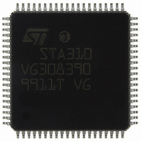
STA310 STMicroelectronics, STA310 Datasheet - Page 28

STA310
Manufacturer Part Number
STA310
Description
IC AUDIO DECODER 6+2CH 80-TQFP
Manufacturer
STMicroelectronics
Type
Audio Decoderr
Datasheet
1.STA310.pdf
(90 pages)
Specifications of STA310
Applications
HDTV, Players, Receivers, Set-Top Boxes
Voltage - Supply, Analog
2.5V
Voltage - Supply, Digital
2.5V
Mounting Type
Surface Mount
Package / Case
80-TQFP, 80-VQFP
Audio Codec Type
MP3 Decoder
No. Of Dacs
3
No. Of Input Channels
2
No. Of Output Channels
6
Adc / Dac Resolution
32bit
Sampling Rate
192kHz
Interface Type
I2C, Serial, Parallel
Rohs Compliant
Yes
Lead Free Status / RoHS Status
Lead free / RoHS Compliant
Other names
497-8856
STA310
STA310
Available stocks
Company
Part Number
Manufacturer
Quantity
Price
Part Number:
STA310
Manufacturer:
ST
Quantity:
20 000
STA310
How to read the above table:
The first 4 columns list the possible configurations for output formats on the PCM outputs. The 5th column gives
the description of the internal 24-bit decoded, scaled and rounded audio samples as they are stored in memory.
These 24 bits are referred to as d23, d22,..., d0, where MSB=d23, LSB=d0. The last column describes the se-
quence of bits that are output on PCM_OUT according to the selected format.
Example 1: in 16-bit mode, with PCMCONF.ORD=1: In memory, 24 bits are stored, where only the 16 MSB bits
(d23, d22,... to d8) are significant and the 8 remaining bits are 0. This is noted: {d23-d8} {8*0}. The data are sent
LSB first, i.e. d8 is sent first and d23 is sent last. This is noted {d8-d23}. 16 bits only are transmitted per channel.
Example 2: in 20-bit mode (PCMCONF.ORD field is meaningless in this mode), with PCMCONF.FOR=1 and
PCMCONF.DIF=0: In memory, 24 bits are stored, where only the 20 MSB (d23 to d4) are significant and the
remaining 4 LSB are 0.This is noted: {d23-d4} {4*0}. 32 bits are transmitted per channel on the PCM outputs:
the 12 first transmitted bits are d23, the last bits are d23 to d4, where d23 is transmitted first. This is noted:
{12*d23} {d23-d4}.
5.4.2 Clocks polarity selection
The polarity of the PCM serial output clock, SCLK and the polarity of the PCM word clock LRCLK are selected
by the field SCL and INV respectively, in the PCMCONF register.
5.4.3 I
To output I²S compatible data, the PCMCONF register must be configured as follows
5.4.4 Sony format compatible outputs
Figure 16. SCLK Polarity
Figure 17. LRCLK Polarit
28/90
PCMCONF.DIF
PCMCONF.FOR
PCMCONF.INV
PCMCONF.SCL
PCMCONF.FOR
PCMCONF.INV
LRCLK
2
S format compatible outputs
LRCLK
PCM_OUT0, 1, 2
SCLK
Left
= 1
= 1
= 1
= 0
= 0
= 0
INV = 1
y
Right
SCL = 0
not right padded,
I²S format,
do not invert LRCLK,
do not invert SCLK.
Sony format,
Invert LRCLK.
LRCLK
PCM_OUT0, 1, 2
SCLK
Left
SCL = 1
INV = 0
Right


