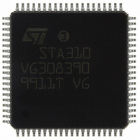
STA310 STMicroelectronics, STA310 Datasheet - Page 45

STA310
Manufacturer Part Number
STA310
Description
IC AUDIO DECODER 6+2CH 80-TQFP
Manufacturer
STMicroelectronics
Type
Audio Decoderr
Datasheet
1.STA310.pdf
(90 pages)
Specifications of STA310
Applications
HDTV, Players, Receivers, Set-Top Boxes
Voltage - Supply, Analog
2.5V
Voltage - Supply, Digital
2.5V
Mounting Type
Surface Mount
Package / Case
80-TQFP, 80-VQFP
Audio Codec Type
MP3 Decoder
No. Of Dacs
3
No. Of Input Channels
2
No. Of Output Channels
6
Adc / Dac Resolution
32bit
Sampling Rate
192kHz
Interface Type
I2C, Serial, Parallel
Rohs Compliant
Yes
Lead Free Status / RoHS Status
Lead free / RoHS Compliant
Other names
497-8856
STA310
STA310
Available stocks
Company
Part Number
Manufacturer
Quantity
Price
Part Number:
STA310
Manufacturer:
ST
Quantity:
20 000
Address: 0xBF
Type: R/W
Software Reset: 0x01
Hardware Reset: UND
Description:
This register must contain a NDIV value that enables
the audio PLL to generate a frequency of
ofact*176KHz for the PCMCK.
Default value at soft reset assume:
– Oversampling factor (ofact) = 384. PCMLCK =
– External crystal provide a clock running at
INIT_RAM
STa310 boot Done
Address: 0xFF
Type: RO
Software Reset: 1
Hardware Reset: 0
Description:
This register is used to signal when the STA310 has
finished to boot. After a soft reset or a hardware re-
set, the host processor must wait until INIT_RAM
hold the value “1”.
The host can then start to configure the STA310 ac-
cording to its application.
PLLMASK
PCMCLK mask for half sampling frequency
Address: 0x18
Type: W
Software Reset: NC
7
7
384 x SF (where SF is the sampling frequency)
27MHz
6
6
5
5
4
4
3
3
2
2
1
1
RAM_INIT
HALF_FS
0
0
Hardware Reset: 0
9.7 Channel delay set-up registers
The six delay setup registers are used to set the rel-
ative delays to the (up to) six loud speaker channels
in order to give the sound effects of, for example, a
large room or to compensate for the listener not being
in the centre of the loud speaker system. The sum of
the delays on the channels must be less than or
equal to 35ms.
The unit for the register delay contents is a group of
16 samples.
Each register value is chosen using the expression:
desired channel delay’*’sampling frequency’/16 sam-
ples and taking care to ensure that the sum of the ’de-
sired channel delays’ is not more than 35ms.
For example, when the sampling frequency is 48kHz,
the sum of the values programmed in the six delay
registers must be less than or equal to:
When only one surround channel is present (in Pro
Logic or other mode), the right surround delay must
be cleared, and the left delay channel is used for both
surround channels.
LDLY
Left channel delay
Address: 0x57
Type: R/W
Software Reset: NC
Hardware Reset: UND
HALF_FS If the incoming bitstream is encoded with
Bitfield
7
35 ms * 48 KHz /16 samples = 105.
6
half sampling frequency, the device
generates a PCM clock (for audio DAC)
1: At 256 x half_fs or 384 x half_fs (half_fs
is equal to 24KHz, 22.05KHz, 16KHz).
0: At 256 x fs or 384 x fs (fs is equal to
48KHz, 44.1KHz, 32KHz).
This function is mainly use for DAC
frequency adaptation.
5
4
Description
3
2
1
STA310
45/90
0


